Bidirectional motor with pwm

coparu67

Senior Member
Hi
I'd like to control the speed of a bidirectional motor with pwm.

1) Which circuit or module do I need? I usually work with the 18M2.

2) Should be posible to implement it with a CHI035?
With this board I know how to implement a bidirectional motor, and how to implement a unidirectional motor with pwm. But not both at once.
 

Puuhaaja

Senior Member
No problem at all. I have done it using l298 motor driver chip an picaxe 18m2

goto main
low b.2
pwmout B.3, 99, 240 ' B.3 sends now 60% duty cycle
' So motor speed is now 60% forfard

pause 1000

' Let's reverse everything
high b.2
pwmout B.3, 99, 160 ' B.3 send sow 100% - 60% = 40 %
'duty cycle and goes backwards with 60% speed
pause 1000
goto main
 

Bill.b

Senior Member
Use the Enable pin of the L298D connected to the PWM output of the picaxe to control the speed.

Bill
 

coparu67

Senior Member
Thank you!
I've used B.6 (and B.7) because CHI035A has the L298D conected to B.4-B.7.
All worked fine.

It´s a pity B.4 is not a pwm pin to get a second bidirectional motor on this board
:)
 

hippy

Ex-Staff (retired)
I think the problem is that the CHI035 board doesn't give access to the PWM enable pin.
Quite a silly oversight on that board design.
Just the way the board was designed way back when; four FET drives and four control lines for two bi-directional motors. That's simple but it's what most users of the board want and seem happy with. It would need extra links and components adding to be able to use it as originally intended and to enable PWM speed control.
 

erco

Senior Member
You can always bit-bang PWM-ish signals for speed control if your program is simple enough.

 
Last edited:

erco

Senior Member
The program from that video demo isn't handy, but basically you send a continuous series of rapid on/off pulses to vary the duty cycle and control motor speed (via H-bridge or FET). 100% duty cycle is full speed, 50% is half speed, 0% is off. Here's some simple code to ramp up & down continuously, where a motor/LED is switched ON by a HIGH 4 command, and OFF by LOW 4:

Code:
DO
for b0=0 to 20    ' RAMP UP 0% to 100%, b0=motor on time, max 20 ms
b1=20-b0           ' b1=motor off time=20-motor on time

high 4                   ' motor on
pause b0               ' on time delay from 0 to 20 ms
low 4                    ' motor off
pause b1               ' off time delay from 20 to 0 ms
next                      ' end ramp up loop (motor off at loop exit from that last LOW command)

for b0=0 to 20    ' RAMP DOWN 100% to 0%, b0=motor off time
b1=20-b0           ' motor on time=20-motor off time

high 4                   ' motor on
pause b1               ' on time delay from 20 to 0 ms
low 4                    ' motor off
pause b0               ' off time delay from 0 to 20 ms
next                      ' end ramp up loop (motor off at loop exit)  

LOOP
https://www.youtube.com/watch?v=aQXhiQZk0so
 
Last edited:

inglewoodpete

Senior Member
I you're using an L298, I don't understand why you wouldn't use PWM from the PICAXE on the enable pin. I've used it many, many time without problems.
 

inglewoodpete

Senior Member
I had overlooked the fact that the OP was trying to implement this on a CHI035/A board. Many of the original Rev-Ed boards are very restrictive in the modern environment. And since Leg 12 (pin B.6) is already in use driving one of the h-bridge inputs, I wouldn't use the CHI035/A at all.

But then, I was responding to using an L298 driver which was also discussed.
 

premelec

Senior Member
Slightly OT - can the TI DRV8825 be used to drive a DC motor forward and reverse though intended for steppers? Thanks...
 

erco

Senior Member
Slightly OT - can the TI DRV8825 be used to drive a DC motor forward and reverse though intended for steppers? Thanks...
I would say no/not easily based on a quick glance at https://www.pololu.com/product/2133

Reliable high-current solid state H bridges can be very hard to scratch build. An easier old school workaround is to use a DPDT reversing relay with a single heavy duty MOSFET or RC speed control. Still takes two I/O pins for full control and common sense (don't reverse at high speed).
 

premelec

Senior Member
@erco - so the main difficulty with the DRV8825 is reversing? Could use two - one for each direction - I like the MOSFET structure... I've got piles of relays but noise and size not appealing. - BTW how did you get that motor to be so noisy? :)
 

erco

Senior Member
@erco - so the main difficulty with the DRV8825 is reversing? Could use two - one for each direction - I like the MOSFET structure... I've got piles of relays but noise and size not appealing. - BTW how did you get that motor to be so noisy? :)
It's a dedicated stepper driver, so the internals are programmed for sequentially driving a stepper's 4 coils. Not sure how you would even wire up a DC motor. AFAIK you can go the other way, using a L298N H bridge to drive one stepper instead of 2 DC motors, because the pins are all accessible and your micro has to handle all the coil switching.

Funny that you noticed the growling noise in that motor video. The way I had it programmed, the motor was dynamically braking (instead of coasting) in the off position. See https://www.youtube.com/watch?v=fL0O0_5ef_k and read description
 

premelec

Senior Member
It doesn't seem to me the chip 'knows' or 'cares' [anthropomorphism strikes again!] what one of it's driver outputs is connected to... so it would drive a DC motor in accord with polarity connected... not the best choice of chips - I think there were some good MOSFET H bridges but I've lost the part numbers... I like the RDson compared to darlingtons... whatever works - with least dissipation...
 

Puuhaaja

Senior Member
I you're using an L298, I don't understand why you wouldn't use PWM from the PICAXE on the enable pin. I've used it many, many time without problems.
In my board design picaxe 18m2 has connection only with four links between L298. That's the reason why I'm not using enable pin. I have connected enable pins to logic supply voltage and now I need only 4 links with Picaxe instead of 6. Hopefully you understood what I tried to explain.
 

inglewoodpete

Senior Member
In my board design picaxe 18m2 has connection only with four links between L298. That's the reason why I'm not using enable pin. I have connected enable pins to logic supply voltage and now I need only 4 links with Picaxe instead of 6. Hopefully you understood what I tried to explain.
Yes, I'm catching up fast :).
 

erco

Senior Member
It doesn't seem to me the chip 'knows' or 'cares' [anthropomorphism strikes again!] what one of it's driver outputs is connected to... so it would drive a DC motor in accord with polarity connected... not the best choice of chips - I think there were some good MOSFET H bridges but I've lost the part numbers... I like the RDson compared to darlingtons... whatever works - with least dissipation...
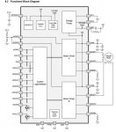
Hmmm, we're not trackin'. Chip diagram attached. The controller internally manages all the switching and pulses to 2 seperate stepper coils, alternating polarity to microstep the motor continually in the chosen direction. Which coil will you connect the DC motor to, and what happens when you feed those alternating polarity signals to? How will you reverse the DC motor?

Steppers & DC motors are very different animals. Horses for courses. :)

stepper.jpg
 
Top