Best way to hack a push button switch?

hookset

New Member
Here we go again - trying to improve my Game camera project some more. I would imagine there is a better way than using a reed relay to simulate pushing a button.
any thoughts on the subject would be welcome.

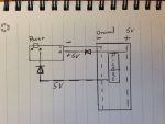
Currently I open up whatever I am hacking and wire to both sides of the push button switch. Add in a reed relay and boom it works just fine.

If I meter the switch, I see voltage. While the button is push it will go to 0v, then back positive on release of the button. normal for most setups.

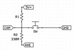
So how is the best way to active the switch from the picaxe chip?

Thanks.
 

hookset

New Member
So if I have positive on one side of the switch and ground on the other. If I apply positive to the ground side it should activate. for some reason the camera i am working on will not. in fact it shorts out the battery, and I have to recharge it before trying aging. not like shorting out batteries. something else is going on here.
 

premelec

Senior Member
Please try measure the _current_ or _resistance_ it takes to actuate the switch being closed - it's possible an opto isolator with FET output could work well for you. [low power solid state relay]
 

SAborn

Senior Member
If you have not killed it by applying positive to a negative in your testing (dead short), i would suggest it has a pullup resistor on the output side of the switch, hence a positive meter reading of voltage supplied through the pullup resistor, and a direct negative or ground (same) on the otherside of switch.

How this works is when the switch is closed it sinks the voltage from the pullup and takes the input low.

Many circuits use this pullup method, and a NpN transistor across the switch works just as well as the reed relay.
 

Mattcad

New Member
Not 100% sure what you are doing, but how about one of these?

http://www.jaycar.com.au/productView.asp?ID=ZC4016

I used one of these with a picaxe and a cheap digital camera to make my scale model red light camera. All I did was wire each side of the push button to the input/output of the switch and the control to the picaxe output of my choice. My thinking was that all the push button does is short the two contacts, so if I can emulate that I do not need to know how the push button is configured. Works fine on my project and nothing has blown up yet. I even managed to catch a few people running the red light =)
 

techElder

Well-known member
Hookset, where did you get the idea that forcing the "ground" connection "positive" was going to work? This suggests a problem with your fundamental knowledge of electronics. Read up some more on basic electronics, and you'll see where your mistake is.

SAborn has it right.
 

hippy

Ex-Staff (retired)
I would imagine there is a better way than using a reed relay to simulate pushing a button.
I would argue a reed relay is the best way if you do not have, or cannot fully reverse engineer, the circuit being interfaced to.
 

hookset

New Member
Saborn,
Thanks for pointer. and I agree, its the whole sinking voltage concept that I am trying to fully understand. Thought this would be a good learning experience.

Clod,
you are correct in that I am very new to electronics. The project I am currently working on is one of my real world learning projects. I just finished watching a You Tube video where they did the exact same thing I am doing but to a different camera. "4 wire Hack".

Not sure why yet... but it works. I will draw out what I have and post it.
 

hookset

New Member
photo.JPG
without drawing everything in, this is what I have. on the drawing, "power" is the power button. when I send a high command from the picaxe to the power button it connects the circuit. What threw me (and it should not have), was measuring voltage across the button and getting a reading. I am new yes, but not sure what I was thinking last night - the light bulb just came on. A clear head and strong coffee does wonder.
 

SAborn

Senior Member
Im not sure what the diode in your circuit is doing, as it appears to be backwards if my thinking is correct.

Then this is all guess work as we really dont know what the camera circuit actually is.

In the schematic below R1 is the pullup resistor within the camera, and R2 is a suggested test you could try, as it appears from your drawing both camera and picaxe share a common power supply, you should be able to use the picaxe direct to sink the pullup (R1) with taking the picaxe pin low.

R2 is used to limit the current to the picaxe pin, as we dont really know the camera circuit, also if the picaxe pin is high and you press the switch on the camera then you would cause a dead short of the picaxe pin to ground without a limiting resistor in series.

camera switch.JPG
 

Goeytex

Senior Member
I hate guessing, but sometimes it is necessary. It is generally a good idea to take some measurements to try to understand an unknown circuit before attempting to interface a Picaxe or any other device to that circuit.

IF the Camera switch is an SPST type that supplies a logic level signal when closed and a high impedance when open, then this can be duplicated with a diode coupling from the Picaxe to the switch input.

I do not imagine that the power on switch needs to source or sink any substantial amount of current to turn on the camera ( Guess). I imagine (guess) that the camera switch supplies a high logic signal to turn on the camera. This can be proved with a meter at test point in Diagram 1 below.

With the camera off and the meter connected as shown... press the camera switch.

If the signal is initially low and then goes "high" when the switch is pressed, then the switch supplies a positive voltage ( Probably ~ 3.7V). If the switch supplies a positive level then Diagram 2 should work.

If the signal is initially "high" and then goes low then my guess was wrong and the switch supplies a ground to turn on the camera. If the switch supplies a low level, then Diagram 3 should work.

The diode coupling mimics an SPST switch, assuring a high impedance to the camera circuit when the logic switch is "off".

This all assumes that a low current logic signal activates the camera.
 

Attachments

hookset

New Member
Gorytex,
Thanks for that advice! I'll test that out, right now I am using a NPN as a switch and its working. the down side is that I have twice as my wires.

Thanks for all the advice - learning is so much fun..
 
Top