Best way to generate an accurate 1Hz signal?

Tvmender

Active member
Hi All

I am trying to reduce the hardware needed to run my Nixie Clocks by using a PICAXE to generate the 1Hz clock signal.

I know there is the I2C option with an accurate external clock source but I want to modify an existing clock which uses an old 16C84 I built back in my college days so no room for "luxuries" unfortunately.

I know this will involve using an externally clocked PICAXE but whats best? How accurate are internal delays?

Sorry if this is a very noob question, I haven't made anything which requires such accuracy until now.

Thanks!
 

inglewoodpete

Senior Member
The only current PICAXE chips that can utilise an external clock source are the 28X2 and 40X2. By using a ~32.....kHz (can't remember the exact figure) crystal and clock-driven interrupts, you should be able to get a reliable 1-second pulse rate. Just thinking about it, I'm sure there are two 16-bit variables associated with the X2s' TIME function, so you should be able to use an 8MHz crystal. X2s use a different configuration for the timer.

I've only used an X2's timer interrupts for 50, 80 and 100mS but you should be able to configure 500mS interrupts for a 1Hz square wave signal.
 

radiosparks

Member
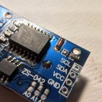
Be careful using this module. Mine came with a CR2032, not the rechargeable one.
I just moved this resistor (201) to disable the charging circuit.

25954
 
Last edited:

Buzby

Senior Member
You could use one of those little GPS modules that directly provide a 1 sec pulse. If you use a little Picaxe as well, you could process the GPS serial to provide the time for a self-setting clock. How you would get this GPS time into your existing setup I don't know. Maybe use the Picaxe I/O to drive the time setting buttons, or directly manipulate the counters if they are discrete.
 

sages

Member
Those are raw PIC examples, programmed in assembler, not Picaxe BASIC.

Still, they are clever bits of code !.
OP mentions adding a pickaxe but has original code in a 16c84, so potential to modify original code which I'm speculating is either in assembler or compiled C.
 

Buzby

Senior Member
Without knowing how much of the 16C84 the OP has already used, we can't know if there is room for the Roman Black code.

No matter if the code is in the 16C84 or a seperate chip, what the code actually does still depends on a very accurate crystal source. The code is intended to overcome the 'drift' of intervals in chips which don't have clocks which are easily divided by 12 or 60. It can't be any more accurate than the source crystal.

I don't think you can beat a proper clock module for long term stability.
 

erco

Senior Member
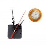
Another long electromechanical workaround just for fun: Some of these cheap $1 clock movements have second hands that tick once each second. (others have smooth continuous motion) One AA battery lasts a year. Hack into a ticking one and grab the pulse that moves the hand.


Attachments

AllyCat

Senior Member
Hi,

Often those clock movements reverse the drive polarity each second, so you might need to be a little creative. ;)

Cheers, Alan.
 

eclectic

Moderator
15 years old this week


e
 

Tvmender

Active member
Many thanks everyone for the replies. I am going to do some tinkering and see what I can get working with an RTC module. I will post my results as soon as I have something.

Thanks again!
 
Top