Beginner coding: toggling pins

Sodapep

Member
Hello!

First post; first code! I don't have a picaxe to try it out on, but I thought I'd run it past the picaxe brain trust.

Overview:

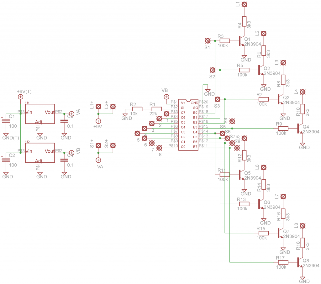
I have a 2x4 array of NO momentary buttons which, upon closure, supply 5v. Each switch is destined to control two switches in a CD4066 (datasheet). One CD4066 switch will toggle an audio signal, the other will toggle a 5v or 9v supply to illuminate an LED. There are 8 buttons and 4 CD4066 (16 spst, two for each button). The bridge between the push switches and the CD4066 is the 20X2 - 8 inputs and 8 outputs.

Code:

SYMBOL LED1 = 0
SYMBOL LED2 = 1
SYMBOL LED3 = 2
SYMBOL LED4 = 3
SYMBOL LED5 = 4
SYMBOL LED6 = 5
SYMBOL LED7 = 6
SYMBOL LED8 = 7

main:
if pinC.7 = 1 then toggle LED1
pause 10
end if
if pinC.6 = 1 then toggle LED2
pause 10
end if
if pinC.5 = 1 then toggle LED3
pause 10
end if
if pinC.4 = 1 then toggle LED4
pause 10
end if
if pinC.3 = 1 then toggle LED5
pause 10
end if
if pinC.2 = 1 then toggle LED6
pause 10
end if
if pinC.1 = 1 then toggle LED7
pause 10
end if
if pinC.0 = 1 then toggle LED8
pause 10
end if
Any comments about the code? Might it work or is there a better way to use the 20X2? Thanks for any comments and recommendations!
 

Buzby

Senior Member
Hello, and welcome to the forum !.

I don't have a picaxe to try it out on ..
No problem, just run the simulator in the Programming Editor.

The first thing you will see is that your code only runs once. You need a loop to repeat

The second thing you will see is that if you hold a button down the LED toggles continuously.

Working in the simulator is a great way to debug !.

Good Luck,

Buzby
 

westaust55

Moderator
Welcome to the PICAXE forum.


The SYMBOL definitions for the 8 LED outputs will default (due to the PE pre-defined constants) to PortB pins but for the X2 parts, it would be better to be more explicit with for example

SYMBOL LED1 = B.0​

As an alternative concept you could read all 8 PortC inputs into a variable in a single pass.
Keep a previoous copy in a second byte variable.
Then using the Exclusive-OR (XOR) math function you can in effect test the two value (new and previous) for any change and put the reult into say byte variable b0 where you can access each bit variable.

Finally based upon the results of the XOR function you can then toggle only the outputs that have had a change of state.
With the XOR function, in comparing new and pervious data bits, if there is no change in input state, the result is a zero (0) and if there was a change of state either low to high or high to low, the result will be a one (1).

There is a presumption here that outputs are to stay on until the same button is pressed again.
Or, do you in fact want a "radio button" style selector where making a selection clears all other outputs?
 

Sodapep

Member
Buzby - Thanks for the tips! I just added the goto main line at the end, which makes it work great! Except for the holding down will constantly toggle the switch haha. But progress is progress.

westaust55 - Thank you for the detailed XOR function explanation. I will need to read up on it, as I don't quite understand it yet. Your presumption is correct. All 8 switches are to be independent of the others.

boriz - thanks for the tip. I'm a little confused as to how the CASE command can toggle the output. It seems like it can cause the output to be high when the button is pushed, but goes back to low when the button is released?
 

Sodapep

Member
Ok, how about this? Seems to work on the sim. Does the picaxe actually run through the code so slowly? Or is that just so debuging/seeing what is going on is easier?

b1 = 0
b2 = 0
b3 = 0
b4 = 0
b5 = 0
b6 = 0
b7 = 0
b8 = 0

main:
button c.7,1,200,100,b1,1,SW1
pause 10
button c.6,1,200,100,b2,1,SW2
pause 10
button c.5,1,200,100,b3,1,SW3
pause 10
button c.4,1,200,100,b4,1,SW4
pause 10
button c.3,1,200,100,b5,1,SW5
pause 10
button c.2,1,200,100,b6,1,SW6
pause 10
button c.1,1,200,100,b7,1,SW7
pause 10
button c.0,1,200,100,b8,1,SW8
pause 10
goto main

SW1:
toggle B.0
goto main
SW2:
toggle B.1
goto main
SW3:
toggle B.2
goto main
SW4:
toggle B.3
goto main
SW5:
toggle B.4
goto main
SW6:
toggle B.5
goto main
SW7:
toggle B.6
goto main
SW8:
toggle B.7
goto main
 

nick12ab

Senior Member
Ok, how about this? Seems to work on the sim. Does the picaxe actually run through the code so slowly? Or is that just so debuging/seeing what is going on is easier?
The real PICAXE will run the code more quickly. You can increase the simulation speed with the Simulation Delay option on the Simulation tab in the Options dialog.
 

Paix

Senior Member
@Sodapep. The CASE statement is a more elegant replacement for the cascaded IF statements in your original code. Once a test has been satisfied it can ignore the remainder, unlike your string of IF statements which would all be tested in turn willy nilly.

An additional observation, if I may be permitted?
The idea of using one signal to control two switches in a CD4066 is sound, but I suspect that you will not be able to control a power source directly, but will need to operate a switching transistor or similar, as the quad bilateral switches are designed for signal processing and not designed to handle substantial currents intended to power LEDs etc.

I may be wrong and am happy to be corrected if that is so :) holding my breath now!
 
Last edited:

Sodapep

Member
nick12ab - thanks!

Paix - thanks for the tip about switching the power. I'll give it a try as I have some CD4066's to spare, but could I just use the 5V output that is switching on and off the 4066 to turn an LED on and off as well? Seems like an easier solution than using a switching FET
 

nick12ab

Senior Member
but could I just use the 5V output that is switching on and off the 4066 to turn an LED on and off as well? Seems like an easier solution than using a switching FET
Yes you could, as long as the current consumption of the LED isn't too high (has to be less than 20mA). Remember to use a resistor if the forward voltage of the LED is less than the supply voltage of the PICAXE (which it will be).
 

Sodapep

Member
Hi all! Sorry to resurrect my thread, but I FINALLY got around to this project. Thanks again for all the advice last year. Here we go with new problems!

Here is my code:

Code:
b1 = 0
b2 = 0
b3 = 0
b4 = 0
b5 = 0
b6 = 0
b7 = 0
b8 = 0

main:
	button c.7,1,100,100,b1,1,SW1
	button c.6,1,100,100,b2,1,SW2
	button c.5,1,100,100,b3,1,SW3
	button c.4,1,100,100,b4,1,SW4
	button c.3,1,100,100,b5,1,SW5
	button c.2,1,100,100,b6,1,SW6
	button c.1,1,100,100,b7,1,SW7
	button c.0,1,100,100,b8,1,SW8
	goto main

SW1:
	toggle B.0
	goto main
SW2:
	toggle B.1
	goto main	
SW3:
	toggle B.2
	goto main
SW4:
	toggle B.3
	goto main
SW5:
	toggle B.4
	goto main
SW6:
	toggle B.5
	goto main
SW7:
	toggle B.6
	goto main
SW8:
	toggle B.7
	goto main
And schematic being used:


For those just joining, I have a 8 button NO momentary SPST switch array that all have 5V on one side. When closed, the 5V connects to one of the 8 inputs on pins 3-10. The code should trigger the corresponding output with a high or low to the transistor, completing and lighting the LED circuit.

I have a startup code that I didn't post, but it's a string of pause, low and highs that flash the LED's in some patterns. THAT works, so the output voltage of PICAXE is causing the transistor to connect the LED's to ground. The problem I'm having is having the switches toggle that output voltage. When a button is held down, I do measure the voltage on the input pins of the PICAXE, so voltage is getting there as well. That leads me to a code problem! And ideas? I'm going to research the CASE command recommended earlier, maybe that will help.

EDIT: upon reading the commands references for the button command, it seems I may need a pull down resistor, 10k from input pin to ground. This is so the input isn't floating? Could this be a cause for my problems?
 
Last edited by a moderator:

JimPerry

Senior Member
EDIT: upon reading the commands references for the button command, it seems I may need a pull down resistor, 10k from input pin to ground. This is so the input isn't floating? Could this be a cause for my problems?
Yes :D

All inputs must be held in the opposite to what you want (HI held LOW or LOW held HI) otherwise your Picaxe input will "float" and get really confused. :confused:
 

inglewoodpete

Senior Member
Just looking at the circuit, I think the 100k base resistors are a little on the high side. Depending on the gain of the 2N3904 transistors, you may not get much more than about 5mA to drive your LEDs. This may be enough but I suggest you use something like 22k or 10k for the base drives.
 

Sodapep

Member
Yes :D

All inputs must be held in the opposite to what you want (HI held LOW or LOW held HI) otherwise your Picaxe input will "float" and get really confused. :confused:
I'll be fixing that up and see if it works! Thanks so much!

Just looking at the circuit, I think the 100k base resistors are a little on the high side. Depending on the gain of the 2N3904 transistors, you may not get much more than about 5mA to drive your LEDs. This may be enough but I suggest you use something like 22k or 10k for the base drives.
Thanks for the advice. I have had all the LED's light up during the opening display and they all seem pretty bright. They are white superbright LED's if that makes a difference. I haven't had all of them on at once which may make a difference. I'll have a look once the code gets up and running.

Thanks again everyone.
 

westaust55

Moderator
Further to IWP’s comments about the 2N3904 transosrtos,

Looking at the 2N3904 datsaheet: http://www.futurlec.com/Transistors/2N3904.shtml
The DC gain ( HFE ) at Ic =10 mA is 100 to 300 but by Ic =50 mA the minimum has dropped to 60. So lets assume around 80 min to 100 max at 20 mA.

For the transistor to be driven into saturation to keep Vce to a minimum and also heat dissipation to a minimum from the datasheet for Ic = 10mA, Ib = 1 mA so we are looking at a value of HFE(sat) of around 10.

So for Ic – 20 mA into the LED then Ib = 2 mA.
Unless going for max brightness, then Ic of around 12 mA my suffice and Ib = 1.2 mA.

To determine the PICAXE to transistor base resistor value for LED current of 21 mA
(Vcc – (transistor Vbe)) / Ib = (5 - 0.75) / 1.2 = 3.54 kOhm so use a 3.3 kOhm resistor.
Transistor power dissipation = Vce(sat) * Ic = 0.25 * 12 = 3 mW as heat.

By comparison with 100 kOhm base resistos, Ib = (5 – 0.75)/ 100k = 0.04 mA.
Led current = Ic = Ib * Hfe = 0.04 * 80 (to 100) = ~3.2 to 4 mA.
With even this small current, power dissipation is Vce * Ic = 1.0 * 4 = 4 mW
Had you been aiming for 20 mA out of saturation mode the power (heat) dissipation would be 1 x 20 = 20 mW. If you have 8 LEDs on at once that equates to 160 mW of heat.

So in summary and food for thought, for more current you need a greatly reduced transistor base resistor value and then drive the transistor into saturation to also reduce heat losses (= wasted energy).
 

Sodapep

Member
It works! It works very well, actually. Thank you all for your help. Now it's time to move on to make switches switch :p I'm thinking about going with 9V relays rather than the CD4066.

westaust55

Very interesting. I assume these values change if I add on a relay to each of the transistor switches? Since the relays will require more current to switch, I suppose it will.
 

westaust55

Moderator
Yes the starting point is always to determine the load current (from datasheets) and the the transistor gain to finally determine the transistor base resistor.
Many small relays have a current draw around 10 to 30 mA depending on the relay (for example physical SI e and number of poles/contacts).
 
Top