Backup battery control

Disaster plus

New Member
Hi,
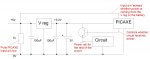
I'm trying to build a PICAXE controlled clock with a graphical LCD screen. The whole circuit will run off a 5VDC mains adaptor, regulated to 3.3V (I'm using the 3V PICAXE X2 variants). I want the clock to continue counting if the power is unplugged though, but the rest of the circuit (LEDs, LCD) to turn off to save battery power.
The circuit I have attached is how I'm thinking I might do this at the moment, will it work? This way the lithium cell can charge during normal operation, and only power the PICAXE when the main power is disconnected.
Thanks
 

Attachments

Andrew Cowan

Senior Member
Just a thought - may some of the devices draw power through the picaxe? Why not use a RTC chip with battery facility (eg DS1307).

A
 

Dippy

Moderator
Can you tell us more about this battery.

Are you talking about a standard lithium coin cell or similar?

So you have no 'control' over battery charging?

If all the above is true then your circuit will live up to your user name :)

Can you tell us your electronics skill level, that will help people ajust their responses to you.

Is it a school poject?

And yes, the DS route would enable you to make a better device.
 

Disaster plus

New Member
I've just finished school, so my electronics level isn't bad. The battery I was thinking of was just a standard 220mAh Lithium coin cell.
I looked at some of the dedicated clock chips, but as I would need a PICAXE in the circuit anyway to control the GLCD and the user interface buttons/menu, I thought I might as well do all the timing internally with the PICAXE (crystal resonator for better accuracy).
What I originally wanted was to have a diode separating the rest of the circuit from the battery and the PICAXE, but I couldn't find one with a low enough Vf.
 

Andrew Cowan

Senior Member
How do you intend to do the timing? Using a 'wait 1' for every second will give very poor results as the LCD and other code takes time. Using trial and improvement to get his value correct (eg pause 924), will be better, but you're still going to lose/gain a few minutes every day. In a week, you'll be 30 minutes out.

If you want it to keep time as well as a watch or household digital clock, yo need to use some sort of timekeeping chip. The most common one to use with PICAXE is the I2C DS1307. Plenty of example code available. This has the facility for a lithium button cell backup. As Dippy says, your method will just make the lithium cell explode after a few days. Also, make sure you know what voltage he LCD needs - most won't shown anything unleess they have exacltly what he datasheet says they need.

A

Schotky diode have a very low Vf.
 
Last edited:

Disaster plus

New Member
LCD needs 3.3V hence the 3.3V PICAXE. And I was going to compensate for the time used displaying LCD data. If the chip runs off a 16MHz resonator it will have a 64MHz operational clock (40X2-3V). If I assume, very very roughly (and probably excessive), that each line of basic code is equivalent to 4 assembler code lines, and I know that it takes 4 clock cycles to process each assembler line, then each basic command can be executed in 67ns. if i work on an error margin of 1 second known error per day, then this allows me 15000000 lines of basic processed a day by the chip, so basically the execution of the basic isn't going to affect the timing that much. Then to send data to the LCD I would need to send a single pulse of a known length that could then be compensated for in the timing program.
You're right though, it would get a bit messy. Ill have a closer look at some of those clock chips.
 

MartinM57

Moderator
If I assume, very very roughly (and probably excessive), that each line of basic code is equivalent to 4 assembler code lines
'fraid not. It fact nowhere near and the relationship of assembler code lines to interpreted PICAXE BASIC is a) undocumented b) variable, depending on all sorts of things

and I know that it takes 4 clock cycles to process each assembler line
Depends on the line of assembler

then each basic command can be executed in 67ns.
That would be very nice - but I think you're about about two orders of magnitude out

it would get a bit messy. Ill have a closer look at some of those clock chips.
Good idea!
 

Dippy

Moderator
It is, by far, the best solution.
And you promise us you won't try charging lithium batteries straight off a regulator?

Whatever, you do, always get product Data Sheets and try and read them. I know they look daunting to start with, but you'll pick it up as you go along.
 

westaust55

Moderator
Another point with the original circuit. When the mains is off, there will be some backfeed from the 3V battery through the voltage regulator.
You might see around 2.0-2.2V at the input to the voltage regulator.
That might also be enough to stop the PICAXE seeing the loss of mains and thus flatten the back-up battery rapidly with LCD still on.
Also greater current drain on the battery from the losses back into the voltage regulator.

But if you are now going to a DS1307 RTC then the above becomes info for future reference only.
 
Last edited:

westaust55

Moderator
If Disaster Plus has an AXE033 LCD module as the mentioned LCD, then an RTC and backup battery can be fited to the AXE033 module.


DP does mention "LCD needs 3.3V. . ." which tends to rule out the AXE033 however

More information from DP would be helpful in making suggestions.
 

BeanieBots

Moderator
Have a very good read of the chosen RTC datasheet.
For example, if thinking of using the DS1307, you will have major problems using it at 3v3 with a 3v3 backup battery.

Also, any attempt at charging a 3v coin cell, will at best, result in a very corrosive mess!
 
Top