Hi All,
Here's a quick, easy mod, that can save a lot of grief. I have the AXE091 development board, which has a single 7 segment LED on it. It is pinnned out to a header WITHOUT current limiting resistors. I also dabble in Basic Stamp and have their development board which has five 7-Seg LED's - but their board HAS resistors.
So, I figured that before I blew the display, I would add resistors. A dremel tool cutoff wheel slices the perfect slot between the connections and leaves just the right gap to solder in a surface mount resistors. While I was at it, I did the servo signal line as well (not shown in photo) since all the docs I have call for a 300 ohm resistor there too. I didn't have 300 ohm, but I did have 330 ohm. They work just fine.
They're so small that it took some time with tweezers and my magnifying headset, but it worked out great. Much less risk now of releasing the magical blue smoke that makes solid state devices work
Regards, John.
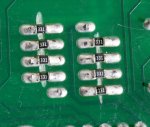
Attachments
-
 70.5 KB Views: 96
