Now before you go "Why not just get the FRM010 or use an 18M2 preprogrammed with the AXE133 firmware", here are some reasons for doing this:
The reason why you would need a pinout is if you had prototyped and already completed your code using the AXE033 and have then found that having a serial backpack makes it too bulky and it would be better to move the driver IC on to the same PCB as the rest of your circuit. (My preferred method is to use the next size PICAXE up and a parallel LCD or OLED but that is slightly harder to interface and can't be done if all the pins on the 40-pin PICAXE are already used!)
The AXE033IC will work with any HD44780-compatible LCD and OLED including Winstar OLEDs, the AMPY 2001-11 LCD in the Maplin lucky bag, cheap Chinese eBay LCDs, large character LCDs and LCDs that are bigger than 16x2 (the stored messages will still only be 16 characters) as long as they don't have extra Enable lines, plus it will work on 3V / 3.3V too.
The IC's pinout is completely unrelated to the FRM010 - since it's intended to be used on the PCB Rev-Ed could design it to make the AXE033 PCB layout more compact rather than make the pinout simpler - and it had to be designed so that the i2c pins could be used for i2c too.
This pinout was found by checking with a multimeter and when a test circuit was built on breadboard it worked.
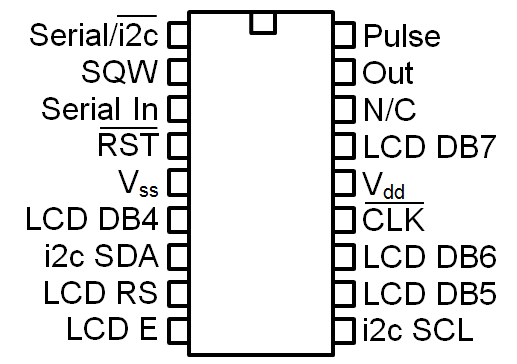
Note that the i2c pins are the same as on the 18-pin PICAXEs.
A horizontal line above something on the pinout means that it's active low - so for the serial/i2c pin it is in serial mode when it is high and in i2c mode when it is low because the line is over the i2c part.
Finally don't forget to fit a decoupling capacitor!
Rev-Ed: If there is any mistake here (especially regarding that N/C pin), please point it out!
- The FRM010 and AXE133 can't be controlled via i2c - so to get an official Rev-Ed i2c driver you have to get the AXE033
- The FRM010 doesn't store messages
- Old school projects tend to have many AXE033 modules and no AXE133 modules because the AXE133 is a recent thing and most (old) school LCD projects tend to use AXE033s so when the uncollected student projects are "recycled"* they end up with some
- The FRM010 and AXE133 can't control the DS1307 which of course can be an issue if pre-X/M2 PICAXEs that don't support i2c are used (extracted from old projects or sometimes still new)
- You accidentally purchased the AXE033-IC from the PICAXE Store instead of the FRM010
The reason why you would need a pinout is if you had prototyped and already completed your code using the AXE033 and have then found that having a serial backpack makes it too bulky and it would be better to move the driver IC on to the same PCB as the rest of your circuit. (My preferred method is to use the next size PICAXE up and a parallel LCD or OLED but that is slightly harder to interface and can't be done if all the pins on the 40-pin PICAXE are already used!)
The AXE033IC will work with any HD44780-compatible LCD and OLED including Winstar OLEDs, the AMPY 2001-11 LCD in the Maplin lucky bag, cheap Chinese eBay LCDs, large character LCDs and LCDs that are bigger than 16x2 (the stored messages will still only be 16 characters) as long as they don't have extra Enable lines, plus it will work on 3V / 3.3V too.
The IC's pinout is completely unrelated to the FRM010 - since it's intended to be used on the PCB Rev-Ed could design it to make the AXE033 PCB layout more compact rather than make the pinout simpler - and it had to be designed so that the i2c pins could be used for i2c too.
This pinout was found by checking with a multimeter and when a test circuit was built on breadboard it worked.
Note that the i2c pins are the same as on the 18-pin PICAXEs.
A horizontal line above something on the pinout means that it's active low - so for the serial/i2c pin it is in serial mode when it is high and in i2c mode when it is low because the line is over the i2c part.
| Pin Number | Name | Description |
| 1 | Serial/_i2c | High = serial mode, low = i2c mode |
| 2 | SQW | SQW output of DS1307 connects here |
| 3 | Serial In | Receives serial data - normally connects to IN pad on header on AXE033 PCB |
| 4 | _RST | Low = Resonator tuning - normally connects to one pad of RST header on AXE033 PCB (other pad is Vss) |
| 5 | Vss | 0V/Ground |
| 6 | LCD DB4 | Connects to LCD data bus pin 4 |
| 7 | i2c SDA | i2c data for DS1307 and for control by master PICAXE |
| 8 | LCD RS | Connects to LCD Register select (Instruction/Data) |
| 9 | LCD E | Connects to LCD Enable |
| 10 | i2c SCL | i2c clock for DS1307 and control by master PICAXE |
| 11 | LCD DB5 | Connects to LCD data bus pin 5 |
| 12 | LCD DB6 | Connects to LCD data bus pin 6 |
| 13 | _CLK | Low = Clock Mode, high = normal mode - normally connects to one pad of CLK header on AXE033 PCB (other pad is Vss) |
| 14 | Vdd | 5V/V+ |
| 15 | LCD DB7 | Connects to LCD data bus pin 7 |
| 16 | N/C | Doesn't seem to be connected to anything and doesn't do anything - Rev-Ed have missed an opportunity here to add a baud rate selector or backlight control |
| 17 | Out | Normally connects to OUT pad on header on AXE033 PCB |
| 18 | Pulse | Normally connects to one pad of PUL header on AXE033 PCB (other pad is Vss) |
Rev-Ed: If there is any mistake here (especially regarding that N/C pin), please point it out!