I have a project (DS1307 Clock/Temp Sensor/Humidity Sensor which requires a 4 line LCD and I wish to use I2C comms so means using an AXE033 . I am unable to buy either the clock/controller Board by itself (to use with my own LCDs) or with a 4 line display from the Picaxe shop. When I telephoned them I was told that I could get the circuit for the controller of AXE033 off the website and all I needed to buy was an AXE033-IC (replacement IC) to build my own.
When I looked on the website there is no circuit for the AXE033 only the aXE133 serial addon board. The chips have arrived and they are not as I first thought based on 18M2 but rather they are PIC 16F819 ics.
I contacted Tech Support who are unable/unwilling to give me a copy of the circuit but suggested I ask here.
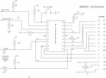
As I previously built up an Axe033 I have tried to trace out the circuit of the LCD clock/controller. See attached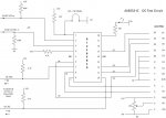 View attachment AXE033-IC.pdf
Has anyone traced the circuit of the axe033 who could check my attempt , as I don't want to blow up another of the PIC16f819s I bought from Rev Ed earlier in the week (nearly £5.00. each)
If you have the circuit of the axe033 I should be grateful for either a copy or confirmation mine agrees with yours.
Regards
Hamtech
When I looked on the website there is no circuit for the AXE033 only the aXE133 serial addon board. The chips have arrived and they are not as I first thought based on 18M2 but rather they are PIC 16F819 ics.
I contacted Tech Support who are unable/unwilling to give me a copy of the circuit but suggested I ask here.
As I previously built up an Axe033 I have tried to trace out the circuit of the LCD clock/controller. See attached
View attachment AXE033-IC.pdfHas anyone traced the circuit of the axe033 who could check my attempt , as I don't want to blow up another of the PIC16f819s I bought from Rev Ed earlier in the week (nearly £5.00. each)
If you have the circuit of the axe033 I should be grateful for either a copy or confirmation mine agrees with yours.
Regards
Hamtech