In this project I wanted to try to imitate some sort of Auto-pilot an Auto-attitude adjuster for a model glider without radio control. I am not sure I have the program correct yet. I was thinking that timing the checking of the switches somehow may be better. I'm not sure it is necessary though. I think this program might be quick enough to flow through the main part. After all, you don’t want the model to be waiting for the next loop of the main program just to get another adjustment to flight. It might be too late! Anyone have any thoughts on that?
I have used a PICAXE 28X2 because it has more than enough input output pins and plenty to spare for future use. What I am trying to do with this auto pilot is to get more forward distance out of my glider and less downward/vertical fall which will make the glider stay in the air longer. With this idea I hope to achieve it.
Simple tilt switches are set up so that they are switched off when the model is level and as soon as the model tips to one side, down forward or tilts up the switches inform the program running in the PICAXE chip what has happened and the program will try to correct the movement back to a glide path. Yaw movement is calculated by the program by analysing the roll and pitch and corrects it.
The system as shown is cheap to implement. It does not have sophisticated sensors and does its corrections from data given in the program which the user can change. This is necessary because not all models have the same flying capabilities. Some are heavier; some lighter, faster, slower or have different servos etc. Therefore it is essential that the user can calibrate their own model with their own data. I have created a starting point of general data which is given in the program for the user to adjust for their model.
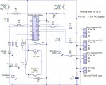
The 28X2 module is light and can work from 7-12V dc from pin 28 and therefore can run off the servo batteries normally at about 8V dc. So no extra batteries!
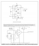
When testing the tilt switches it is very difficult to see if they are on or off so by adding 4 LEDs so that when the tilt switch closes the LED lights. Adjustment can be made and seen when bending the legs of the switches.
I hope this idea will be useful to others and any comments are welcome. One thing I can think of is if the model flies very well you might have a problem getting it back down to earth. You may need some other method. Something to ponder.
Here is the Wire diagram I am using at the moment:
and here is the code I'm using at the moment.
I have used a PICAXE 28X2 because it has more than enough input output pins and plenty to spare for future use. What I am trying to do with this auto pilot is to get more forward distance out of my glider and less downward/vertical fall which will make the glider stay in the air longer. With this idea I hope to achieve it.
Simple tilt switches are set up so that they are switched off when the model is level and as soon as the model tips to one side, down forward or tilts up the switches inform the program running in the PICAXE chip what has happened and the program will try to correct the movement back to a glide path. Yaw movement is calculated by the program by analysing the roll and pitch and corrects it.
The system as shown is cheap to implement. It does not have sophisticated sensors and does its corrections from data given in the program which the user can change. This is necessary because not all models have the same flying capabilities. Some are heavier; some lighter, faster, slower or have different servos etc. Therefore it is essential that the user can calibrate their own model with their own data. I have created a starting point of general data which is given in the program for the user to adjust for their model.
The 28X2 module is light and can work from 7-12V dc from pin 28 and therefore can run off the servo batteries normally at about 8V dc. So no extra batteries!
When testing the tilt switches it is very difficult to see if they are on or off so by adding 4 LEDs so that when the tilt switch closes the LED lights. Adjustment can be made and seen when bending the legs of the switches.
I hope this idea will be useful to others and any comments are welcome. One thing I can think of is if the model flies very well you might have a problem getting it back down to earth. You may need some other method. Something to ponder.
Here is the Wire diagram I am using at the moment:
and here is the code I'm using at the moment.
Code:
;PICAXE Attitude Adjuster for free flight gliders
;No Radio Control just the servos.
;Program by Ken Anderson. 2013 v1.0
;
;directives
#picaxe 28X2 module
setfreq em32 ;external module frequency of 32MHz

;The reason I choose this chip/module is because...
;1. 7-12 supply. (you can use the servo battery normally about 8V)
;2. It has a scratchpad memory for the data table accessable via 1 dimensional array commands
;3. it has the serial input socket already attached and ready to use
;4. it is very light especially as you don't need the extra batteries
;5. it has plenty of spare input/output pins for future use for example:
;			 a. addition of distance sensor from the ground for program landing
;			 b. addition of another servo for an air-brake/spoiler to bring it down to earth
;			 c. air speed sensor so that you can reduce speed when you need to


;Pinouts for information                        N/U = not used
;                serial out  1|¯¯¯|28  VIN (7-12V)
;               serial in    2|===|27  0V
;                      LED   3|===|26  Reset
;                      0V    4|===|25  +5V
;      LED L         <->c.0  5|===|24 b.7<-> LED R
;     R_L tilt sw    <->c.1  6|===|23 b.6<-> Roll right tilt sw
;      N/U           <->c.2  7|===|22 b.5<-> Servo Yaw data line
;      N/U           <->c.3  8|===|21 b.4<-> Servo Roll data line
;      N/U           <->c.4  9|===|20 b.3<-> Servo Pitch data line
;    LED D           <->c.5 10|===|19 b.2<-> interupt pin N/U
;    LED U           <->c.6 11|===|18 b.1<-> interupt pin N/U
;     N/U            <->c.7 12|===|17 b.0<-> interupt pin N/U
;   P_up tilt sw     <->a.0 13|===|16 a.2<-> N/U
;   P_Dn tilt sw     <->a.1 14|___|15 a.3<-> N/U

;variables
symbol P_Up		=	pinA.0	;	pitch up tilt switch
symbol P_Dn		=	pinA.1	;	pitch down tilt switch
symbol L_roll	        =	pinC.1	;	Left roll tilt switch
symbol R_roll	        =	pinB.6	;	Right roll tilt switch

symbol servoRoll	=	B.4		;	Servo data line
symbol servopitch	=	B.3		;	Servo data line
symbol servoYaw         =	B.5		;	Servo data line

symbol LED_Lroll	=	C.0		;	LED for left roll tilt switch
symbol LED_Rroll	=	B.7		;	LED for right roll tilt switch
symbol LED_PDown	=	C.5		;	LED for pitch down tilt switch
symbol LED_PUp          =	C.6		;	LED for pitch up tilt switch

symbol BCD_Pos          =	b5		;	Tilt switch Position indicator in BCD
Symbol ScratchM_pos    =	b6		;	Position in the scratchpad memory of correction info

;INFO.
;1 = high 0 = low value taken from tilt switches
;servo command = one end = 75 centre = 150 other end = 225

;TABLE      Note. BCD          Tilt switches	             Servos
;                               Lr  Pd  Rr  Pu      Roll pitch  Yaw
;level flight		    0   0   0   0   0       150   150   150	               centre positions
;Pitch up only		    1   0   0   0   1	    150   140   150
;right roll only            2   0   0   1   0	    160   150   150
;Right roll + pitch up      3   0   0   1   1	    160   140   180
;Pitch down only	    4   0   1   0   0       150   170   150
;     ----                  5   0   1   0   1	     -     -     -	                Impossible(pitch down+pitch up at same time)
;Right roll + pitch down    6   0   1   1   0	    160   170   75
;     ----                  7   0   1   1   1	     -     -     -                         Impossible(pitch down+pitch up at same time)
;Left roll only             8   1   0   0   0	    140   150   150
;Left roll + pitch up       9   1   0   0   1	    140   140   180
;     ----                 10   1   0   1   0	     -     -     -                         Impossible(Left roll + right roll at same time)
;     ----                 11   1   0   1   1	     -     -     -                         Impossible(Left roll + right roll at same time)
;Left roll + pitch down    12   1   1   0   0	    140   170   225
;     ----                 13   1   1   0   1	     -     -     -	                     Impossible(pitch down+pitch up at same time)
;     ----                 14   1   1   1   0	     -     -     -                         Impossible(Left roll + right roll at same time)
;     ----                 15   1   1   1   1	     -     -     -                         Impossible(Left + right roll+up+down at same time)

;7 positions in BCD not used here but could be used for other tasks


Init:
;put all correctional servo data into scratchpad memory
;NOTE: When trials commence these may need to be changed in order for a particular model to fly as wanted.
;use the serial input from a laptop to change the program data
;this is general data

;    Roll      Pitch     Yaw
put 1,150:put 2,150:put 3,150		;correction level flight
put 4,150:put 5,140:put 6,150		;correction pitch up only
put 7,160:put 8,150:put 9,150		;correction Right roll only

put 10,160:put 11,140:put 12,180	;correction Right roll and pitch up
put 13,150:put 14,170:put 15,150	;correction Pitch down only
put 16,000:put 17,000:put 18,000	;Just for ptr

put 19,160:put 20,170:put 21,75         ;correction Right roll and pitch down
put 22,000:put 23,000:put 24,000	;Just for ptr
put 25,140:put 26,150:put 27,150	;correction Left roll only

put 28,140:put 29,140:put 30,180	;correction Left roll and pitch up
put 31,000:put 32,000:put 33,000	;Just for ptr
put 34,000:put 35,000:put 36,000	;Just for ptr

put 37,140:put 38,170:put 39,225	;correction left roll and pitch down

put 40,000:put 41,000:put 42,000	;Just to complete the BCD
put 43,000:put 44,000:put 45,000	;Just to complete the BCD
put 46,000:put 47,000:put 48,000	;Just to complete the BCD

debug

Main:
;set dynamic variables to 0
b5=0:b6=0

;keep looking at tilt switches and deal with accordingly

IF L_roll=0 AND P_Dn=0 and R_roll=0 and P_Up=0 then: BCD_Pos=0: goto correct_attitude: endif
IF L_roll=0 AND P_Dn=0 and R_roll=0 and P_Up=1 then: BCD_Pos=1: high LED_PUp: goto correct_attitude: endif
IF L_roll=0 AND P_Dn=0 and R_roll=1 and P_Up=0 then: BCD_Pos=2: high LED_Rroll: goto correct_attitude: endif
IF L_roll=0 AND P_Dn=0 and R_roll=1 and P_Up=1 then: BCD_Pos=3: high LED_Rroll: high LED_PUp: goto correct_attitude: endif
IF L_roll=0 AND P_Dn=1 and R_roll=0 and P_Up=0 then: BCD_Pos=4: high LED_PDown: goto correct_attitude: endif
IF L_roll=0 AND P_Dn=1 and R_roll=1 and P_Up=0 then: BCD_Pos=6: high LED_PDown: high LED_Rroll: goto correct_attitude: endif
IF L_roll=1 AND P_Dn=0 and R_roll=0 and P_Up=0 then: BCD_Pos=8: high LED_Lroll: goto correct_attitude: endif
IF L_roll=1 AND P_Dn=0 and R_roll=0 and P_Up=1 then: BCD_Pos=9: high LED_Lroll: high LED_PUp: goto correct_attitude: endif
IF L_roll=1 AND P_Dn=1 and R_roll=0 and P_Up=0 then: BCD_Pos=12:high LED_Lroll: high LED_PDown: goto correct_attitude: endif

goto main

correct_attitude:
;get servo correction information from scratchpad memory
ScratchM_pos=BCD_Pos*3
ptr=ScratchM_pos+1

;b7=@ptrinc	;test purposes
;b8=@ptrinc	;test purposes
;b9=@ptr	;test purposes

servo [45536],4,@ptrinc;roll
servo [45536],3,@ptrinc;pitch
servo [45536],5,@ptr;yaw

;switch off any LEDs
low LED_Lroll:low LED_Rroll:low LED_PDown: low LED_PUp

goto main
end
Last edited:
 fficial&channel=np&tbm=isch&tbo=u&source=univ&sa=X&ei=cTt2UrbYPKSv0QWl2ICoCg&ved=0CE4QsAQ&biw=1280&bih=821