Are 28X2 Inputs TTL or ST?

NoSmoke

Member
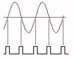
I was contemplating adding an external Schmitt trigger to an input to possibly better detect (less jitter) the zero-cross point of an AC input. I am doing this for software triac triggering on a 28X2 and simply looping until the pin goes hi or lo. It works but the detection point timing seems to wander randomly which makes the triac harder to control, especially at the full off or full on points.

Looking up the Microchip data sheet for the PIC18F25K22, I have found one table that describes the I/O pins as TTL (Sec 1.0, Table 1-2 in the data sheet) and another that describes most of the inputs as ST (eg. Sec 10.0, Table 10-5, PortB).

Can anyone please clarify it for me? If the input(s) are already ST, it doesn't sound like an external ST would add anything(?).
 

srnet

Senior Member
There is a table under the InputType command in the manual.

Referring back to the PIC data sheet, granted its confusing, because the input buffer type depends on the function assigned to the particular PIN.

I assume the table in the PICAXE manual reflect the case when the pins are used as general IO.

I would have though you would have more of an issue with the looping of the PICAXE varying in time, that must be orders of magnitude greater than the switching time of a TTL versus ST input, assuming the input is not very slow moving.

You dont say how you are doing the zero point crossing detection, or how much it is varying, that might provide some clues as to the problem.
 
Last edited:

hippy

Ex-Staff (retired)
There will be some jitter as it takes some time to execute PICAXE commands so if using -

Do : Loop While pinX = 0

The input may go high just before the LOOP condition is tested ( code continues on next line immediately ) or just after ( another DO and LOOP test has to occur before continuing ).

That could give -0/+250us jitter at normal operating speed, -0/+2.5% jitter for a 10ms half-cycle of mains.

Increasing operating speed should reduce the jitter, halve it with each doubling of speed so at fastest speed should have dropped to around -0/+32us, -0/+0.3%.
 

John West

Senior Member
Just for the record, Schmitt triggering circuitry is used on the inputs of a variety of logic chips, certain TTL chips among them. So classifying a chip input as either "Schmitt trigger" or "TTL" isn't really an appropriate description.
 

srnet

Senior Member
Just for the record, Schmitt triggering circuitry is used on the inputs of a variety of logic chips, certain TTL chips among them. So classifying a chip input as either "Schmitt trigger" or "TTL" isn't really an appropriate description.
In general that may be the case.

For PICs however the voltage levels of the switching point (Vil and Vih) are quoted for each input type, see the data sheet.
 

westaust55

Moderator
So classifying a chip input as either "Schmitt trigger" or "TTL" isn't really an appropriate description.
Not sure I follow you there JW

In most IC's (eg in the 74xxx series or 4000 series, etc) a logic chip has inputs dedicated as ST or TTL or CMOS type in terms of logic voltage levels.
In the case of the PIC chips as used for the PICAXE series, as already mentioned, the type of input TTL vs ST may be determined by the use of the input,
For example TTL for general purpose digital input but ST type input for the SR Latch function input.
 

John West

Senior Member
It's just a matter of the common usage of the terminology, Westy. Here in the States at least, the TTL data books are full of an array of chips, some that use Schmidtt triggering, some that don't, yet the chips are still considered to be in the TTL family with the input type being just another characteristic of certain of the chips. CMOS has their own logic books.vPerhaps it's a regional thing and elsewhere all the Schmidtt triggered logic chips are segregated into their own manuals and not called TTL, but I haven't seen it here in the US.
 

NoSmoke

Member
Saborn & srnet, man, I thought I'd seen that somewhere put couldn't find it (I stopped one page to short). Thanks.

Srnet, I'm doing the crossing detection as hippy suggests - waiting for the input to go hi or low (and using Do, Loop to do it).
I also tried Pulsin which worked about the same but had the disadvantage of not allowing generation of a pulse during the half cycle the instruction was operating. Also tried Button and PWM. Button was worse and I couldn't keep the PWM synced at all with the zero cross detect.

Hippy, good point on the loop test timing. It's hard to quantify exactly but it appears the jitter is greater than 2.5% just eyeballing the scope input trace vs the output pulse. The load (incadescent lamp) can also be seen to flicker a bit (brightness varies) esp near the full on or full off points. I'll try increasing the clock speed (at 8Mhz now) and trying a ST input.

John, maybe that's why the Microchip table info seems to be contradictory (at least to me).


Now to figure out which 28X2 I have (looks like the "28X2" has ST on ser-in only and cannot be reconfigured). The "28X2-5V" however has ST on the C pins. I also have a 14M2 on hand though which is configurable so maybe I will have to switch to that one.

What I'd really like to figure out is how to employ the usual type of lamp dimmer triac circuit by replacing the variable resistor with a program controlled device. That way I would not have to be concerned with pulse timing and, timing under changing AC frequency with a wind gen o/p, and, trying to control timing for three triacs in a 3ph circuit. I looked at "digipots" which would seem to work but they are apparently only available in logic level voltages so I don't know how they would work in a circuit contolling 120VAC.

I'm even considering using a servo motor to physically turn the pot (three pots for 3ph?) but that's not a very satisfying solution. I recall someone here also mentioning in another thread using a lamp/photocell to replace the pot.

Thank you for all the help!
 

hippy

Ex-Staff (retired)
I also tried Pulsin which worked about the same but had the disadvantage of not allowing generation of a pulse during the half cycle the instruction was operating.
I would suggest posting your circuit and code as it doesn't seem from that description you're creating a pulse at crossover every half cycle.
 

Attachments

premelec

Senior Member
LDR solution...

I have used the LDR control of phase control dimming but only for single phase - I don't think there's any easy way for 3 LDRs tracking for 3 phase... maybe a pulse transformer with one primary and three secondaries firing the three phases...
 

NoSmoke

Member
hippy, what I did was send multiple trigger pulses (an even number, say 6 or 8) after zero detect by Pulsin which avoided missing one half of the cycle each time around. Of course, the more the pulses the more the timing errors towards the end.


premelec, thanks for mentioning LDRs. I googled and found the following circuit:

http://www.epanorama.net/documents/lights/lightdimmer.html

Scroll down to `Simple voltage controlled dimmer

Did the`LDR have the range to control from full off to full on in your application?


I'm still not clear on the implications of using three triacs for three phases. I see no problem if the phases were isolated (not connected delta or wye) but if connected delta or wye, would the phase interaction cause problems? I BTW have re-examined my 3ph alternator wiring and found that the phases can be brought out separately (there are nine wires coming out to the junction box - three groups of three per phase with the three per phase used to select 120 or 240 o/p (I think)). Only probem is I would have to run another three conductor cable to the wind mill.
 

premelec

Senior Member
LDR

My uses were just substituting the LDR for a pot in a commercial dimmer unit which would have the usual DIAC trigger diode so I don't think they'd go full on. I don't know what you are trying to do - if your three phases are separate one phase probably wouldn't care a lot what the others were doing though this might depend on the machine design. Often times you'd use three phase rectification because the output ripple is relatively low. I've lost track of where and why you are doing what with the 3 ph... :) Sometimes simpler solutions are appropriate rather than trying to get a few % more performance...
 
Last edited:

Goeytex

Senior Member
This code allows a Picaxe X2 to take a commonly used comparator zero cross signal and then
outputs a pulse at each zero crossing. A pot connected to the ADC allows adjustment of the
pulse width.

If this signal is sent to the gate of a Triac, it will do phase angle control of the AC signal
This is for a single phase only but shows one way to do it with a Picaxe using an interrupt.

The comparator circuit is attached.

Code:
#picaxe 20x2
#no_data
#no_table

[B]INIT:[/B]
setfreq m64
symbol int_edge = b0
pause 2000
setint %00000000,%00000100  [COLOR=#008000]'c.2 Low[/COLOR]

[B]MAIN:[/B]
do 
readadc 9,w5
loop

[B]INTERRUPT:[/B]
w5 = w5 * 59 max 14900
pulsout b.7,w5

 If  int_edge = 0 then
 setint %00000100,%00000100   [COLOR=#008000]'int on c.2 High[/COLOR]
 int_edge = 1 
 return
   
elseif int_edge = 1 then 
   setint %00000000,%00000100 [COLOR=#008000]'int on c.2 Low [/COLOR]
   int_edge = 0 
   endif 
   return
 

Attachments

Last edited:

westaust55

Moderator
I was contemplating adding an external Schmitt trigger to an input to possibly better detect (less jitter) the zero-cross point of an AC input. I am doing this for software triac triggering on a 28X2 and simply looping until the pin goes hi or lo. It works but the detection point timing seems to wander randomly which makes the triac harder to control, especially at the full off or full on points.

Looking up the Microchip data sheet for the PIC18F25K22, I have found one table that describes the I/O pins as TTL (Sec 1.0, Table 1-2 in the data sheet) and another that describes most of the inputs as ST (eg. Sec 10.0, Table 10-5, PortB).

Can anyone please clarify it for me? If the input(s) are already ST, it doesn't sound like an external ST would add anything(?).
The pin input "type" is provided in Manual 2 for the general purpose input conditions.
When certain pins are used for other funcitons such as the SRLatch and hINT functions these pins are typically "reconfigured" as ST type.

Thus for the newest (wide voltage range) version of the 28X2 the inputs can be also defined further as:
Code:
[U][/U][B]Input - Type[/B] 
Serin ST 
A.0   TTL 
A.1   TTL 
A.2   TTL 
A.3   TTL 
B.0   TTL   hINT0 = ST  SRI = ST (SRLatch) 
B.1   TTL   hINT1 = ST
B.2   TTL   hINT2 = ST
B.3   TTL  
B.4   TTL 
B.5   TTL   
B.6   TTL 
B.7   TTL 
C.0   TTL   T3CKI = ST (Timer3 Clock)
C.1   TTL 
C.2   TTL 
C.3   TTL 
C.4   TTL 
C.5   TTL 
C.6   TTL 
C.7   TTL
 

Goeytex

Senior Member
I setup a 20x2 to use one of the comparators to do zero cross detection. Configured so that compflag triggers
an interrupt every time the comparator changes states. So an interrupt is triggered at every half cycle using one comparator. The interrupt routine simply does a pulsout and returns. The input to the Picaxe Comparator is simply a current limited and Zener clamped 120V mains signal. ( Be careful with this as it is not isolated.)

This works nicely with very little jitter ....except that (even at 64mhz) due to processing overhead of about 200us
the leading edge of the pulsout signal correlates to about 9 volts on the 120AC signal..... not exactly zero. This was
the first time I had tried to do anything with the comparator function.... nice. If anyone wants to see the code, let me
know and I will post it.
 
Last edited:

hippy

Ex-Staff (retired)
The input to the Picaxe Comparator is simply a current limited and Zener clamped 120V mains signal. ( Be careful with this as it is not isolated.)
It is best to do this taking a feed from a secondary winding of a mains transformer rather than going directly to mains live. It is far safer and avoids having to connect the circuit 0V to mains neutral which presents a danger in itself.

If a PICAXE circuit does connect to mains directly you have to take real care not to inadvertently connect other items to mains, such as a PC through the download cable or test equipment via any 0V probe or contact. It's not only life threatening it could damage or destroy the PC or test equipment.

Best recommendation is to steer well clear of all direct mains interfacing, never use mains unless qualified and experienced, and where it is done use proper safety equipment ( RCD, isolation transformers etc ) and never work alone.

For most people that translates as, "don't do it".
 

Goeytex

Senior Member
I agree that This is not something for the inexperienced to do.

However many of our modern products such as microwave ovens, ranges. etc use non-isolated mains voltage to power the internal electronics & microprocessor using a capacitor based transformerless power supply. This meets all safety codes (UL, CE. etal) because the electronics & wiring are completely enclosed and , cannot be accessed, or touched by the user without removing the covers which include a mains interlock switch.

In my test circuit, current was limited to < 10 ma before ever reaching the proto board, and the proto board was enclosed in an ABS housing where nothing could be touched. If anyone tries to replicate this, as Hippy said, an isolation transformer should be used unless your are an experienced EE with the proper equipment and even then it's a good idea.

Attached is a diagram showing the test circuit using an Isolation Transformer.
 

Attachments

Last edited:
Top