Another Garden Light - This time with Hope(RF)

Hey Guys,

I'm wanting to make a solar powered node for my data logger, and I have chosen to use the HopeRF module.

I read here that the enable pin doesn't actually fix, so after a bit of a steam, I made a work around with a BC337 on the 0v pin.

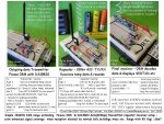
I have a 08M setup with a thermistor, and a sense wire hooked up to the solar cell (Can I use a higher ohm'ed resistor than 10k? I don't want to waste energy from the cell...). The HopeRF unit is set up for transmit and receive on pin 1 and pin 3 (with diode...).

Is the transistor deal all wrong? Should I be switching high or low (+5v or 0v).

The problem is as soon as I wire in the HopeRF module, the 4700uF capacitor holding charge drops from about 5.6 / 5.7 (from the solar light inverter) to about 1.8 in slightly less than a second. I'm sure it's about current draw, (I haven't measure it yet), but it really shouldn't be drawing any, (there is no ground connection until the NPN base is high!).

I haven't drawn up any schematic, but it is simple nough to explain: I have the ground pin wired to the collector, pin 0 (08M) wired to the base, and the emitter wired to ground. No resistors or anything, just point to point. Pin 0 is pulled high when I want to enable the unit (I also have a great looking bright blue LED to indicate when pin 0 is high).

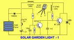
About the actual solar light itself; after reading about UV and moisture on a previous topic, I have decided to make it out of uPVC pipe. I don't want my brand new HopeRF units to be corroded by the moisture... I won't have a clear spot for the light, as that is just asking for trouble. The base will be some type of removeable fiting (maybe a screw type PVC fitting, but maybe just a peice of plexiglass bolted over an O ring...)

Been working on this aspect of the project since yesterday (not all that long =D), but it is the school holidays - so I have plenty of time. If you guys don't reply for a while, I'll be working on the wireless router end (I want my project to twitter, so I hacked an asus router and intalled python).


Long post, but thanks for reading it (or reading the basics!)
 

Dippy

Moderator
"I haven't drawn up any schematic, but it is simple nough to explain"

- simple enough for you as you are sitting in front of it.

It takes 10 minutes for us to convert from text to picture and then we could have read it wrong or you typed it wrong.

Please, please post a schematic.
Help us to help you.
You have "plenty of time" - we might not have such a luxury as school holidays ;)
A schematic reduces chances of ambiguity and prolonged Q&As.

Stick a resistor to the base and without knowing ovrall power consumption it may be too weedy.
 
Last edited:

westaust55

Moderator
Tentatively the low side switching should not be a big problem. Just make sure that you allow sufficient current into the transistor base to put the transistor into saturation which keeps the colelctor to emitter voltage down to around 0.2 volts.

I constructed a mini-weather station but used a keymark 433MHz Tx module (~10mA max current) with a BC548 transistor and low side switching works without a problem. Transistor selection could play a part.

http://www.picaxeforum.co.uk/showthread.php?t=11749&page=2
See post 17.

The BC548 is only rated to 100mA and:
Vce (sat) is 0.2V (typ) with Ic = 100mA and Ib = 5mA
Vce (sat) is 0.09V (typ) with Ic = 10mA and Ib = 0.5mA

The BC337 is rated 800mA and:
Vce (sat) is 0.7V(max) with Ic=500mA and Ib = 50mA.

So BC337 may cause enough volt drop so slightly lower volts to the Tx module to be an issue ? ? ?
 
Schematic:


Hopefully it is clear enough... I usually draw schematic more for building boards.

I actually have a BC547, so I will swap that in... I don't understand the theory behind transistors, so I wouldn't know which resistor to choose...
 

Dippy

Moderator
I don't know any details about your 'inverter' but are you sure that is the best place to take power to PICAXE and RF Module? Already we can see that C1 is not helping you.

Is the solar panel + inverter man enough? Some of the tiddlers are real wimps.

What does D1 do? I don't know the Hope connections.

You really should consider a small resistor to the base. Westy has indicated some base drive calcs.
Suggest you read up on the basics of transistors, there are plenty of school-level websites.

If i was doing this I would use a PNP (or Pchan MOSFET) as a high-sdied switch.
I don't like interrupting grounds on RF circuits.
 

hippy

Ex-Staff (retired)
That's quite a confusing circuit and would benefit from being re-drawn using the tradition of +V as a line at the top, 0V as a line at the bottom.

I'm sure D2 is wrongly placed.

The biggest problem is; what exactly is "Invertor Output", "Temp" and "Solar", the pinout of the HopeRF.

I would suggest minimising your circuit to just powering the TX module on and off, remove everything else for now.
 
Hopefully this is easier to understand:


I'm very sure about D2 and C1. C1 is a 4700uF capacitor, and D2 rectifies the AC output from the solar garden light inverter. This is really the power source for the PICAXE and HopeRF.

D1 got me at first. I was having trouble a while back with serin on on pin 3, so I resorted to the manual. Apparently due to the internal silicon, to use pin 3 for serial comms, we need to have a diode connected like this.

Solar and temp are to do with my sensors. Solar is the + output from the solar panel for measurement, and temp is a small thermistor bead.

I'll bust out the breadboard, and see if I can get my power switch to work.


Thanks for the help guys =) Sorry I haven't been specific enough.
 

westaust55

Moderator
also, if you do not have one fitted (ie just not shown on the schematic) you need to add a 10kOhm resistor to ground (0V) from the Serin pin (physical pin 2)
 

Dippy

Moderator
"I'm very sure about D2 and C1. C1 is a 4700uF capacitor, and D2 rectifies the AC output from the solar garden light inverter. This is really the power source for the PICAXE and HopeRF."

But in your first image your power to PICAXE and Hope is on the inverter side of D2.
So, all those nice noisy sparklies go to the nitty-gritty.
Yes there wll probably be some suppression effect, but you won't get any nice rectifiying/smoothing function like that.
You would need to connect between D2 and C1 for the power to PICAXE & Hope.

Have a look at rectifier circuits if you don't believe me.

And a tip: Put a 100nF ceramic decoupling cap right next to PICAXE power pins for best ADC results.

Maybe post your code too at some stage?

I'm sure you'll get it working.
 

hippy

Ex-Staff (retired)
Much nicer circuit, thanks.

As noted by Dippy, the D2 isn't rectifying AC as shown.

D1 is only needed when the voltage on Pin3 ( or to any series R to pin 3 ) is going to be greater than +V the PICAXE is powered from. Thus it's needed when putting RS232 from a PC through a 22K, but shouldn't be needed in this case when the HopeRF cannot put out more than its supply.

I haven't, so double check the DRX and DTX are correct way round on the HopeRF / PICAXE. Sometimes things like DRX may mean 'the module's receive input', an input to the module, sometimes 'the module's received data', an output from the module. If you have a PICAXE output connected to a module output you will likely have problems. Hence when bread-boarding, don't connect either DTX or DRX to start with, just concentrate on getting power switching working.
 

moxhamj

New Member
We may have to wait for stan for the hope part of the schematic.

I'm still finding it a bit confusing. I've not ever used transistors with no base resistor. Generally, if you use no resistor, you are going to dump whatever the picaxe can supply to ground via the base and probably short the power supply (which has hardly any grunt anyway). Any reason you can't put a 2k7 to 10k resistor on the base?

I'm not sure you can switch low side anyway as that assumes the RS232 lines are open circuit and no power flows when off. Maybe you can configure picaxe pins as inputs but maybe not. A high side transistor switch is just a BC547 and a BC557 and some resistors.

Then there is the solar light inverter. I doubt these can give more than 5-10mA and I think the Hope might need 20mA. Maybe it will work but I foresee collapsing power supply problems and those are notoriously diffucult to debug.

Can you get it all working first with a stable regulated 5V supply?
 

manuka

Senior Member
mm171: Solar garden lamps are great for lighting white LEDs, but their output is usually too rough for micros & hi tech. circuitry. A good deal of massaging is usually first needed, & although higher I comes with lower V, you'll typically only have ~10mW to play with! Most throwaway type solar garden lamps max. ~2mA at ~5V I've found. Naturally this could be tolerated with low duty cycle, so suggest you inform about your node activity & PV details. Being in NZ it's assumed you'll have plenty of sunlight of course!

HopeRF modules draw ~25mA & are picky on supply voltage- see resource page details & circuitry =>http://picaxe.orconhosting.net.nz/hoperf.htm. I guess you know that only the TTL HopeRFs will go into low drain "sleep"? Their RS-232 offerings still draw several mA due to the onboard MAX232.

If only modest ranges are needed, the likes of Jaycar's "Keymark" modules may be easier to use as a repeater. However, like many 433 MHz RX, they too are usually very intolerant about supply (needing 5 ±½ V), so regulation may be called for. Maybe consider several garden lamp PVs across 4 x AA NiCds (a bank of which of course hold 4 x 1.2V = 4.8V closely), with charging via a Schottky lifted from one of these lamps. Colin Mitchell (of "Talking Electronics" fame) has posted many lucid details on garden lamp supply hacks- sample below.

EXTRA: Andrew Hornblow over in Taranaki has done a good deal of WiFi mini-router serial interfacing & HopeRF linking. See => http://picasaweb.google.com/picaxe/CicadaCom# These things are only US$29 in bulk, & with the ever surging $Kiwi are particularly appealing.
 

Attachments

Last edited:
Yeah, the HopeRF got me at first...

I know it's wire right, you are right about the capacitor... I have actually wired it physically to the + and - of the capacitor... Sorry, late night =P

I just assumed D1 was necessary... Originally I used the RS232 version of the HopeRF module, and it wouldn't work without it.

I've got a little experience with the HopeRF modules, (Enough to send data around the place), so I'm pretty sure about the data lines. Confused me at the start, but after a bit of data sheet reading I got it...

I'll BB the power, and see how I go. To giver you guys a bit to think about:

Code:
DisableBOD
DO
SLEEP 4 ' Sleep to begin with charges capacitor
HIGH 0 ' Enable Wireless, high blue LED
READADC 2, b0 ' Read the temperature
READADC 4, b1, ' Read the solar voltage
' Do I need a pause in here?  Apparently ADC affects serial...
SEROUT 1, N600, (#b0, #b1) ' The receiver will take care of the data
LOW 0 ' Turn off "peripherals"
LOOP
The code is also a prototype at the moment, so it is not complete.
 
Didn't see the second page, so double posting is to reply to later two =P

I have considered the solar light power supply, hence the diode and capacitor setup. I have a 4700uF capacitor across the + and - rails on the PICAXE... The diode filters the AC, and the capacitor charges up and up (It stops after about 5.6v, as the PICAXE either 'regulates it', or maybe it is due to the PICAXE waking up at around this point, and dumping a little power into an LED (seems to use a lot of juice... I should put a resistor on that).

I now have a 630ohm resistor on the base, but I can upgrade to 1k. Like I said, I haven't yet learnt how the base affects the current flow, so I'll need to learn about that. Before now, I though of an NPN transistor as a digital switch, like an instant relay.

I like the idea of multiple solar units, so it may be a trip to Dick Smiths to get some twin core wire and The Warehouse to get another couple of units... I feel it would be better to get this to work on the one unit, perhaps I need a bigger capacitor / capacitor bank?

To try and clear things up a bit, the solar inverter (dedicated IC running of a 1.2v NiCd) flows into the capacitor through a diode. The capacitor is 4700uF, and is used to supply both the HopeRF and the PICAXE 08M.

The HopeRF module I have in this unit will be a TTL version.

What is the difference between switching High or Low?
 

moxhamj

New Member
Like I said, I haven't yet learnt how the base affects the current flow, so I'll need to learn about that.

The current into the base is amplified by the 'gain' of the transistor. This is different for every transistor, but for small signal ones it might be 500. The figure in the data sheets is hfe. So you put 1mA into the base and it can switch 500mA. But the max current a small signal transistor can switch might only be 100mA. If 500mA is more than 100mA then the transistor is 'saturated', ie it behaves as a switch. If less, then it behaves like an amplifier.

Also, current into the base is wasted, so there is no need to put more current into the base than is needed. So if you are only switching 20mA and the gain is 500, you might only need 0.1mA into the base. In practice, resistors from 1k to 2.7k come out about right.

Re high side/low side, well if you are switching big loads that would be relevant. But the solar supply might only supply a few milliamps and the picaxe can supply up to 20mA itself, so it may be easier just to directly turn the hope power on and off with a picaxe pin and no transistor at all.

Then again, it probably won't work as the inverter doesn't have enough grunt.

You might be able to store some energy in a big capacitor and send out a brief packet before the cap goes flat (and the picaxe resets etc etc). 4700uF might not be quite enough, and it is the sort of experiment that really needs a CRO.

This stuff isn't easy. I tried for a year to get it to work, and ended up with 12V SLA batteries, standard 36cell solar arrays, off the shelf solar charger/controllers (from futurlec) and LM2575 5V switching regulators to power the picaxe/radio modules. The battery capacity is overkill, but on the other hand, if you only use 1-2% capacity of a battery it lasts a lot longer. Old SLAs from alarm companies and second hand car batteries will last for years in this sort of application. On the other hand, a solar light discharges a cell completely overnight (often by midnight). And a nicad might only be good for 500 charges. So that is 500 days, ie a year and a half. Then it dies and you throw it away and get another one. Or put a new battery in. But then you notice the plastic is going opaque over the solar panel and moisture is corroding the innards and I've not seen many last more than 3 years.
 
Last edited:

westaust55

Moderator
low side transistor switching

As I mentioned in an earlier post I have been using low side switching without problems.
With a BC548/BC549 at least 0.5mA is required to achieve saturation under which conditions the collector to emitter voltage (Vce) is lowest. Since there is referenc e to a load of 20mA lets go for at least 1mA into the base (Ib).
Based upon this I would suggest a resistor in series with the base of not greater 3.9 kOhm and preferably 2.7k or 3.3K.

4.5 V Vcc
0.7 V Vbase
1 mA Ibase

3.8 V Vres
3800 Ohms Rbase
 

manuka

Senior Member
For general bipolar BC547 style transistor work (on say 5 V), base resistor values should of course be quite significant. As < a mA need flow (if that!),with typical gains of several hundred even 1k may be too generous- I usually use 4.7k in fact. I've not further checked your schematics, but Andrew & I have directly controlled HopeRF Pin 6 "enable" from a PICAXE-08M pin anyway!

More the point in this solar garden lamp powered approach,these HopeRF transceivers need a tight supply voltage. As I mentioned earlier, unless they see 5 ±½ Volts they just don't work! As Dr_A will no doubt outline,Yishi offerings are more tolerant in comparison. Stan.
 
Listening to what you have been saying about voltage, the solar inverter have been dropped from the project...

I went to DSE and bought a 4cell battery holder, loaded in some 2500mAh AA batteries, and have two panels wired in series to charge.

4 x 1.2v = 4.8v

The solar panels provide about 6v when in decent sunlight (and it's almost summer in NZ...).

The batteries have been charging this afternoon, and are about 4.9 - 5.0v. I'm hoping this is enough to power the PICAXE and HopeRF.

I've just done a bit of transistor research, and could only figure out that the base resistor should be 1K.

Vsupply / I(mA) = R(kohm)
5 / 5 = 1K

I couldn't find a formula involving hFE...

I don't mean to waste power by using 5mA base current, I'm just not 100% on how much current my circuit draws while transmitting (I would need a scope to find out...) I'll swap a 1kohm resistor into the circuit. I have a bunch of 1k resistors (Andrew sent me a 100 pack one day :D)
 

westaust55

Moderator
I have previously given details for the required PICAXE to transistor base resistor at post 16.

If you are using a BC548 transistor in saturation, from the datasheets, the base voltage Vbe(Sat) will be 0.7V above the emitter which is at 0V. Thus the PICAXE to base resistor will be Vcc – Vb = 4.5V – 0.7 = 3.8V or 5V - 0.7V = 4.3V

By forcing the transistor into saturation, at acts more as a switch than an amplifier so no need to consider Hfe.
0.5mA is sufficient base current to saturate the transistor with a 10mA load. Others have suggested the HopeRF module is around 20mA.
Datasheets do seem to vary between manufacturers but lets use Ic/Ib = 20 at saturation. (Other sheet have 10 as a value). SO at 20mA load current (=Ic) 1mA is sufficient base current.
So the base resistor max value would be Vres (= 4.3V) / Ires (1mA ) = 4300 Ohms or 3.8V/1mA = 3800 Ohms
Then suggest select a slightly small value so 2.7k or 3.3k is adequate.
 

manuka

Senior Member
Ok & similar sunbeams here in Wellington- very welcome after that big storm in fact! If you are using 2 PVs ex solar garden lamps, then they only put out ~2V each when loaded. Thus 2 in series will only be ~4V, which will NOT charge 4 x 1.2V (= 4.8V) AA NiCds! You'll need 3 in series to have enough grunt to push any charging current. Even go for 4 to allow for overcast & off angle illumination- the bright sun charging current will only be ~10mA anyway. For more current you'll need more PVs in series/parallel- use an ammeter to check.

What is the duty cycle of this setup anyway - you've still not said. If on (say) 10% of the time then an average system drain may be ~ 3-5mA at 5V. As a rough rule (to allow for wet days, off angle sunshine & of course night time) a simple PV charger should provide in bright sunshine 3 times this average current. Go for (at 10%) 5V x 25mA = 125mW. This is approx 4 solar garden lamp 2V- 25 mA panels in series. Stan
 
Last edited:
Thanks for taking the time to teach me "the way of the transistor". Now I know how to figure it out in future :).

Vres = Vsupply - Vbe
R = Vres / Ires

Therefore

Vres = 5.0v - 0.7v = 4.3v
R = 4.3v / 1.0mA = 4.3k

1mA is enough for up to 50mA from what I could tell. So a 3.3k resistor should do the job nicely. I'll pick some up tomorrow.

I did a breadboard test, I can flash an LED and power a HopeRF module with my solar-charged battery pack. So tomorrow's (hopefully tonight's to be honest..) job is to mount all of the electrics into a 'dual tube' PVC enclosure made from uPVC. I have two round solar panels, so I will have two tubes screwed to a single stand. The wires will pass underneath, as this will be easier to seal than the side. To mount it, I figure if I; drill a pilot hole, fill it with silicon, and then screw the bolt on, I should be able to get a nice seal.

I'm not sure about internal moisture... I don't want condensation on the inside of my 100% air tight container. Perhaps I will sit it next to the dehumidifier for a couple of hours before screwing on the lids...
 

BeanieBots

Moderator
I agree with Manuka that a 6v (open circuit) solar output will not be very effective at charging 4X 1.2v NiMH batteries. IMHO you will require another panel. Also, I'll take his word for it about only only requiring a panel of ~X3 average current in NZ sun. For the UK this needs to be ~10X to ~12X.

For moisture, consider adding a small descicant sachet. Many products come with one so should be easy to get hold of one and an hour in the oven at about 90C will recharge them.
 

manuka

Senior Member
BB: That x3 is a minimum & I'd recommend x5 for more critical setups. You can never dismiss the likelihood of falling leaves, bird droppings or damage masking a PV section!

FWIW NZ is much more equatorial than Sth. UK, being akin to California/Italy/Spain. Most NZ regions get 2000-2500 bright sun hours p.a., but coastal temps rarely get above 30°C or below 10°C due to the moderating effects of the vast surrounding oceans.

In spite of (at times) chilly winter days, I've never been anywhere with year round sunshine as intense as here. It's no doubt due to NZ's very clear skies (& long debated ozone holes), as even in winter the sunbeams can be so strong that folks wear sunglasses. Due to skin cancer concerns sunhats are essential for kids during much of the year too.

Plug for NZ sunbeams completed. Stan.
 
I tested the open voltage of the series cells, and they produced about 6.3v. The short circuit current of the two cells is about 35mA.

Now, they duty cycle... If I have it every hour, the duty cycle will be about 0.041% (1.5s MAX per hour) If I have it every 2 hours, the duty cycle per hour becomes about 0.02%.

The average system drain *I think* will be 1.23mA if every hour, and 0.6mA if every two hours. The panels themselves will produce an average current (based off the short circuit current, and 5h of full sunlight per day) of about 7mA? ( (5 * 35mA) / 24hours )

Great tip for a desiccant package... I'll get one of those out of an old shoe box for sure!

I'm still optimistic of this working... I'm hoping not to have to buy more panels.
 
 
Last edited:

Dippy

Moderator
I haven't checked them, but remember the info you have.
Will a 5V capacitor be happy being charged to over 6V?
You know the current usage of your circuit and the duration.
You know that you'll need X volts for Y seconds.

Somewhere a regulator may be needed.

So you should be able to calculate the min capacitance to give to the required oomph for the required time. Remembering capacitor discharge curves.

It was only a suggestion to think about, there may be better ways.

PS. If you wait then BB will work out your required capacitance for you. But there are probably oddles of electronical websites that show how to work it out. If you have a calculator with ln and recip on it then you can do it yourself.
 
I have no idea how to calculate the required capacitance...

How about a zener diode across the + and - ? That way when the voltage gets to 5.6v, the extra power is dumped.

A super capacitor looks like a cheapish alternative... An added bonus is they are very small!
 

manuka

Senior Member
MM: Splutter- that duty cycle is so low as to be near trivial, & leakage losses etc will be more significant! All this sweat as well ... this looks a perfect supercap application. Jaycar sell quite a range, but I've a stash here (somewhere !) if you're pushed. Think they're 2.5V however.

Capacitor maths 101. Do you know Q=VxC = I xt ? This means 1 Farad at 5V = 5 Coulombs & could provide 100 mA for 50 seconds, or 10mA for 500 seconds ( ~10 mins) etc. However cap. discharge is NOT linear, so the terminal Voltage would soon fall too low in this case to sustain HopeRF work. Even so you should get maybe a few minutes at 10mA, or maybe ~30secs at ~30mA. With your super low duty cycle this looks ample.

N.B. As a rule of thumb I've found Open Circuit Voltages from PVs will drop by about 2/3 when loaded into a matched rechargeable battery. Hence a so called 12 V PV may show ~20V Voc until connected. I speculate hence your 6 Volts will drop to 4V (thus 2 series PVs?) when loaded to a NiCd quartet. You'll need 3 or even 4 in series IMHO- the cells will cope OK given the tiny currents.

Stan. in Wellington.
 
Last edited:
Time to buy a super capacitor then... I guess I was get a 0.047uF capacitor, should be plenty for 1.5 seconds worth of output.

I'm going to boost the duty cycle if the parts permit, buy seeing as I'm measuring temperature and solar energy, I'm not concerned.

manuka said:
Do you know Q=VxC = I xt ?
Nope, not sure how to read that equation either... Q(?) = voltage x current = current x time? Q is charge maybe? I haven't done physics since last year, and electricity was just the bare basics (ohms law covered the whole unit...). I'm used to having a powerful battery, where the only problem that ever arises is that the micro doesn't do what it is meant to. This is a bit of a theory step up, so I really appreciate you guys teaching me this stuff!

I figure a 6v solar cell array will easily charge a 5v super cap... Maybe I should get a 5.6v zener diode, and use the original solar inverter - it has 1 - 2 hours to charge the capacitor!
 

moxhamj

New Member
Lots of progress here. Re caps, supercaps do have a higher internal resistance than standard caps. But it probably doesn't matter here. Tests will check that out.

I can never remember the formula so I work back. 1F discharging 1A =1V per second. 0.047F at 1A is 1/20th of a second to drop 1V. 20mA = 50 times that so a bit over 2 seconds. You are in the right ballpark if the data packets are short. 4700uF is 0.0047F which is a bit low. If you can get higher supercaps than 0.047F then that is better. If they are 2.5V ones like Stans, you can put two in series.

For testing, charge up your supercap to 5V, then send one data packet and see how many volts you have left. Ideally, something like 4.9V.
 
Looking at Futurlec Australia, the price including shipping is going to be about $6.75AUD. At the moment that will convert to about $8.20. The 1F capacitor is actually one of the cheaper ones... 1F 5.5VDC. I'll buy a 5.6v zener diode too.

If I were to get the same 1F capacitor from Jaycar, it would cost more than that, not including shipping!

I'm thinking of sending 6 bytes...

serout 1, t600, (85, ":Q", #b0, #b1, b2
b2 is a simple addition check sum. (constant + b0 + b1)
 

manuka

Senior Member
MM: Save your money! Drop me your postal address & I'll mail you a couple of supercaps (just unearthed - they're small electroytic sized cylindrical low ESR PowerStor Aerogel Series A 1 Farad 2.5V ). In return you can help an old lady across the road- or let Wellington win the next Shield game. Stan.
 

Attachments

Last edited:
A stubborn Andrew Hornblow, and a quick bench test proved that the enable pin works just fine.

The HopeRF module draws 25mA for about 100mS while it starts up. It will continue to draw 20mA in an innactive awake state. If I put it to sleep, the unit will instantly draw only 18 - 20uA.

So I'm thinking the duty cycle can become much higher on the wireless sensor. I may as well make it similar to the charging rate of the capacitor with the inverter.

I'll have to do the maths with the solar panel charging the NiCad, and me using power from the inverter.

I also need to figure out how to create a 24hr inverter... I would like this unit to be running 100% of the time (even though it will be sleeping for much of the time..) The solar panel is wired to the dedicated IC only. The panel doesn't get forwarded onto the battery. I suspect the sense pin and the connection to the battery are inside the IC. I'll see what happens if I wire the cell across the battery, and disconnect that particular pin. Then it will be time to figure out current usage for the solar inverter... Maybe I should wire in a zener diode to simulate sunshine when the capacitor gets high enough... I'm hoping a simple high value resistor going from the + of the capacitor to the sense wire will do the trick, as this would certainly be easier.
 
Last edited:

BeanieBots

Moderator
Very generous of manuka to supply the caps.
I was going to mention that there are super caps and then there are those whimpy little things that pretend to be super caps used for memory backup.
What manuka describes are the real deal.

They typically only have a 2.5v max rating.
As Doc says, you can put two in series but a little caution is required.
No two caps will ever have identical values and their internal leakage will also differ. Eventually, this will lead to all the voltage being across only one of them. The 'normal' solution is to fit a resistor across each one but in your app that would waste power. I've found that fitting an LED across each cap works as a 'visual' zener as well as keeping them balanced. Choose a colour to give the required voltage and/or add a series diode for an extra ~0.5v.

Don't forget C (total capacitance) will be halved with two caps in series.
 
If this doesn't work, I guess I can make an order for a single supercap. The ones on Futurlec are rated for 5.5v and 1F.

500mF vs 4.7mF... If Andrew managed to get his to work on a 4700uF (He used a 'jaycar' wireless unit) then I'm sure i can make it work with 0.5F.

Could two capacitors wired in series be dangerous to the other? What it sounds like you are saying is that one capacitor ends up will all of the voltage... Is there a good way to fix this? I'm not sure what you mean by the LEDs... Are you saying I should put an LED in parallel with each capacitor to hold down the voltage?
 

moxhamj

New Member
Is there a good way to fix this? - yes several. BB's led idea at the right voltage (blue leds?) - in parallel with each capacitor. Or a 10k/10k voltage divider. But it is much easier to try to get a 5V supercap if you can.
 
Maybe it would be better to place an order in to futurlec then... It will cost about $10NZD inc. shipping and a 5.6v zener diode...

I will have 1F capacity rather than 0.5F capacity also...
 
Top