Slowly bringing the pieces together
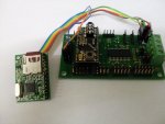
Two photos here.
First one is an SD21, a 28X2 module, and a uALFat module.
To fit the 28X2 I need to do a few things.
1. Cut the pins 13,14,15,16 from the 28X2. If I need them then I will bring them out on a socket ontop of the board
2. Cut the traces on the SD21 to pins 5 & 6 on the Basic Stamp socket.
3. Connect the trace that went to pin 5 to pin 9 of the Basic Stamp socket
4. Connect the trace that went to pin 6 to pin 8 of the Basic Stamp Socket
5. I then reconnected 28X2 pins 5 and 6 to the Header on the left hand sidr so I can access them later.
As I have a group of servo's about 8 inches away from this board and I did not want to run the power all over the place I decided to cut the power pins off the servo sockets for Servo's 2-7, and bend the control pins back so I can slip a socket onto them. Where the Servo's are I have a power distribution point.
As the UalFat module needs 3v I put in a 3.3V regulator (Upper right hand side of SD21, and soldered the Vin and Gnd pins to the I2C connector. Then bent the Vout pin up so that I could plug a connector onto it.
Now... The Programming :>
Enjoy..
Dave
Attachments
-
 48.3 KB Views: 127