Again need help Read write external data with eeprom and 18m2 picaxe

lamxe

Senior Member
Dear All
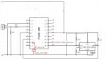
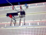
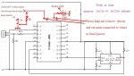
I would like to play and learning :how write and read EXTERNAL data from eeprom 24c16 or 24c256 with picaxe code.Please see photo Thank you
I wish to read write only a few byte with 24c16 for easy start but I don't know how writing the code. I have tried this code (don't care over write or other problem just see the code is work or not) but led not blinking ( is mean no data out). . Please help me correct this code and show me how connected in out data to 18m2 .I hope you understand my need your help and will help me.
Sincerely many thank you
lamxe
Code:
#PICAXE 18m2
'
Symbol i2cAddr24LC256 = 100000  '

b0 = 0	'Initialise byte variables
b1 = 1
b2 = 2
b3 = 3
'
hi2cSetup i2cMaster, i2cAddr24LC256, i2cFast, i2cWord
Do
   hi2cOut 0,(b0, b1, b2, b3) ; (DATA IN) 'Write values to bytes 0-4 of EEPROM . EXTERNAL 1hertz square wave
   Pause 50
   Inc b0
   Inc b1
   Inc b2
   Inc b3
   hi2cIn 0, (b4, b5, b6, b7)  ;(DATA OUT)'Read values back from EEPROM .LED blink if right code 
   Debug
   Pause 2000                 'Wait 2 seconds
Loop
 

Attachments

Technical

Technical Support
Staff member
Symbol i2cAddr24LC256 = 100000
is not correct try
Symbol i2cAddr24LC256 = %10100000
 

lamxe

Senior Member
Dear all and Technical.
Thank you for your help. I am sorry When programmed is right code as you point me . But I wrong type when posted .
After tried many code but don't see data out ( by led or multi meter ) I return used a simple code on manual but still not success . Please could you help me explain why don't work. Thank you so much'
lamxe
//////////////////////
#picaxe 14m2 ; 24lc16

;Data in (1Hertz) connected to B.0 (leg 13 of14m2) data out(led +R) connected to B.1 (leg 12 of 14m2)

hi2csetup i2cmaster, %10100000, i2cslow, i2cbyte

main: hi2cout 0, (b0) ; Write data to eeprom
pause 20 ; Wait for write to complete

hi2cin 0, (b1) ; Read data from eeprom
debug ; Show result

pause 1000 ; Wait a short while
b0 = b0 + 1 ; Increment the data to write
goto main ; And repeat
 

hippy

Ex-Staff (retired)
Please post photographs of your circuit. If writing an incrementing single byte to a single location does not work then it may be that your circuit is not wired or powered correctly.
 

lamxe

Senior Member
Code:
	hi2csetup i2cmaster, %10100000, i2cslow, i2cbyte

main:	hi2cout 0, (b0)		; Write data to eeprom
	pause	20		; Wait for write to complete

	hi2cin 0, (b1)		; Read data from eeprom
	debug			; Show result

	pause 1000		; Wait a short while
	b0 = b0 + 1		; Increment the data to write
	goto main		; And repeat
send to forum Hippy NEW.JPGsend Hippy.JPG
Please post photographs of your circuit. If writing an incrementing single byte to a single location does not work then it may be that your circuit is not wired or powered correctly.
Dear Hippy and All..
I have tried with 20m2 -18m2 -14m2 _24c16 with this simplest code but led all time stay off (is mean Data not be save ?). So please help me again.Many thank you
 

hippy

Ex-Staff (retired)
Your WP (pull-down), SCL and SDA (pull-up) resistors appear to be misaligned with the Eeprom chip in the photograph.
 

lamxe

Senior Member
Your WP (pull-down), SCL and SDA (pull-up) resistors appear to be misaligned with the Eeprom chip in the photograph.
Dear Hippy .
Is right place but when take photo it has been detached and I reset not right place.I am sorry. And as rossko said: (There is nothing in your code to turn a LED on. What were you expecting to see happen? ) I think is right so Please could you help me again by give me this code . Sincerely Thank you
//////////////////
Hi rossko57
#There is nothing in your code to turn a LED on. What were you expecting to see happen? #
I think so but I don't know how writing the code for see detect( led) Could you help me to get it please . Thank you alot.
///////////////
Hi JimPerry
Thank you for your advice me .
 

rossko57

Senior Member
I don't know how writing the code for see detect( led)
It is rather up to you, what would you LIKE the LED to do?
I suppose for this little test, you might have it light up for a second each time you read back good data from the eeprom?
So you could write some code that checks to see if the data read is what was expected (i.e. what was written a little while ago) ; then if it is good turn on the LED, pause for a second, then turn it off. Else if it is not good, turn off the LED, and pause a second. Then goto the next test.

Keywords IF, THEN, ELSE, PAUSE.
 

lbenson

Senior Member
We are still unable to tell if the hardware setup you are testing is correct--the photo you posted is clearly wrong. Please post again a clear photo showing the correct placement of the pullup and pulldown resistors.
 

lamxe

Senior Member
Thank you nick12ab and rossko57 for your time help me.
Dear lbenson.
We are still unable to tell if the hardware setup you are testing is correct--the photo you posted is clearly wrong. Please post again a clear photo showing the correct placement of the pullup and pulldown resistors.
Doing bad but I have tried connected data(1 hz) in to hserout and hserin with and without pullup and pulldown (4k7) but led always off (no data out ?), So last time please help me. Thank you
AveoStill0003 new.GIFAveoStill0004 new1.GIF
 

lamxe

Senior Member
Dear nick12ab.
Thank You for your ready to help .But very sorry I don't have experience to post a good photo (limit size image on forum ). I like to build this circuit action exact as MP3 but with smallest memory(few bit or byte ) ie: download and play MP3 = write and read = picaxe 18m2+ 24c16 with write (external data not internal data please see schema) = 1 or 0 (HL) pulse and play = see data out = led of few bit or byte. . Now I trying again with other code . If you understand what I wish to do please help me to got other code when you have the time,
Thank you so much
 
Last edited:

lbenson

Senior Member
Your first photo was clear enough, and showed the faulty wiring. Another similar photo should show whether the wiring is now right.
 

nick12ab

Senior Member
But very sorry I don't have experience to post a good photo (limit size image on forum ).
You need to upload your photo as a JPG like you did in post 5, then it will comply with the file size limits.

Your photos in post 13 are far too small, making it difficult to verify which rail the resistor in the top left is connected to, which PICAXE pin the resistor below it is connected to, or even how many legs the second resistor has!
 
Top