Hi
I have recently began working on a project to convert a generic foot pedal to be wireless and connect to a wireless receiver which is connected to a PICAXE which will control a brushless motors controller.
I have decided to use the ERF modules as the wireless link and I have written some very simple code which at the moment allows the user to adjust a POT connected to 08M2. The READADC command reads the voltage from the POT and then PICAXE outputs the data to an ERF. The second ERF receives the data, sends it to another 08M2 which then outputs the corresponding value via sertxd to the PE terminal. This all works well and as a test program I am happy at the moment.
The next stage in my project was to strip the foot pedal I purchased of Ebay. Its a generic 240V sewing machine foot pedal.
I was hoping to adapt some of the components within and attach my test circuit to the pedal however I have come up against a hurdle right at the start!. (Please bear in mind that I am very novice at electronics so please stick with me)
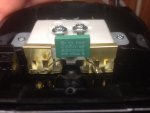
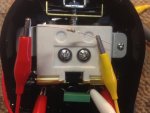
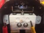
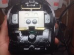
The Foot pedal seems simple but I was expecting a POT within in, however it has some sort of resistor controlled by the pedal which only has two terminals. When I measure the resistance across the terminals I get 0 - 2K ohms depending on how far in the peddle is pushed. I thought I would be able to apply a voltage (5V) to this component and then use the readADC to measure the output. However this is not the case as the voltage taken from the component is either 0V or 3.8V depending on the position of the pedal and there seems to be no gradual increase or decrease as I would expect with a POT with 3 terminals.
I have included some pics to help and my questions are:
1) What is this component called, that is the large white mass at the ctr of the pic.
2) Is there anyway I can get this to work given the components at hand and my limited knowledge of electronics.
Thanks very much for your help and I appreciate you sticking with me as this is a bit long winded.
I have recently began working on a project to convert a generic foot pedal to be wireless and connect to a wireless receiver which is connected to a PICAXE which will control a brushless motors controller.
I have decided to use the ERF modules as the wireless link and I have written some very simple code which at the moment allows the user to adjust a POT connected to 08M2. The READADC command reads the voltage from the POT and then PICAXE outputs the data to an ERF. The second ERF receives the data, sends it to another 08M2 which then outputs the corresponding value via sertxd to the PE terminal. This all works well and as a test program I am happy at the moment.
The next stage in my project was to strip the foot pedal I purchased of Ebay. Its a generic 240V sewing machine foot pedal.
I was hoping to adapt some of the components within and attach my test circuit to the pedal however I have come up against a hurdle right at the start!. (Please bear in mind that I am very novice at electronics so please stick with me)
The Foot pedal seems simple but I was expecting a POT within in, however it has some sort of resistor controlled by the pedal which only has two terminals. When I measure the resistance across the terminals I get 0 - 2K ohms depending on how far in the peddle is pushed. I thought I would be able to apply a voltage (5V) to this component and then use the readADC to measure the output. However this is not the case as the voltage taken from the component is either 0V or 3.8V depending on the position of the pedal and there seems to be no gradual increase or decrease as I would expect with a POT with 3 terminals.
I have included some pics to help and my questions are:
1) What is this component called, that is the large white mass at the ctr of the pic.
2) Is there anyway I can get this to work given the components at hand and my limited knowledge of electronics.
Thanks very much for your help and I appreciate you sticking with me as this is a bit long winded.
Attachments
-
 93.7 KB Views: 57
 -
 81.5 KB Views: 32