Adding fixed mS time to an input frequency?

jbsmith1

New Member
Hi, I would like any help please.
I have the following program that trigger's from a variable clocked input signal and then produces a timed length output ref the pot value.
How could I add code to add an additional fixed amount of time to a specific frequency as well as the added time ref the pot value.

i.e Input triggered frquency 2.0Hz, then add time from pot value and also add fixed 10ms time, and so..
2.0Hz add pot value and 10ms
1.9Hz add pot value and 20ms
1.8Hz add pot value and 30ms

Here is my code so far, but I don't know what is needed to get the results above:

SYMBOL LED1 = 0
SYMBOL POT1 = 4
SYMBOL TRIGGER = pin3

SYMBOL Temp = B1

START:
ReadADC POT1, Time 'get pot value between 0 and 255

IF TRIGGER = 1 THEN START:

HIGH LED1
FOR TEMP = 1 TO Time
PAUSE 1
NEXT TEMP
LOW LED1
GOTO START:
 

inglewoodpete

Senior Member
I can't say I fully understand your challenge. You refer to adding (extending) time of a frequency. Time and frequency are different things, although inversely related.

Take the 2.0Hz frequency you first refer to. I'm assuming that you referring to a square wave: the 2.0Hz is made up of 250mS high followed by 250mS low and the pattern is repeating. I'm presuming that you want to add time to the waveform, in the first case add 5mS to the high and 5mS to the low: basically changing the frequency of a single cycle of the square wave (to 1.96Hz). Your output will be out of sync with the input - what happens then? When the outgoing square wave cycle is complete, the second incoming one will already be underway.

Perhaps you can clarify what you are ultimately trying to achieve.
 

jbsmith1

New Member
Hi, thank you for your help.
Yes looking back at what I wrote, I can see it reads odd lol.

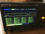
I have attached a picture (hopefully) of my scope screen showing the input Hz signal (green) and what my circuit then does to it (yellow).
The input frequency can change from 6Hz to 1Hz in 0.1Hz steps and my circuit will output the same frequency but with a longer duration which I can adjust with a pot.
But, what I'm now trying to do, is at specific frequencies, add a fixed time to my output value?
Any help or guidance really appreciated.
 

Buzby

Senior Member
The first part of what you ask for is easy, it's just a pulse triggered by the falling edge of your input signal.
The width of the pulse could be adjusted by a pot very simply.

Your second request, pulse width related to input frequency is a bit more involved, as now you have to measure the input frequency in order to select a pulse width. As your maximum input frequency is quite low, only 6Hz, it should not be too difficult.

Here is a bit of code to do your first requirement, i.e. pulse triggered on falling edge, width adjustable by a pot.
Run this in the simulator first to get feel for how it works, then adjust for your application.

Code:
#picaxe 08M2

symbol InputSignal  = pinC.1
symbol OutputSignal = C.2
Symbol AnalogInp    = C.4
Symbol InputCopy    = bit8
symbol InputOld     = bit9
Symbol FallingEdge  = bit10
Symbol PWidthCount  = b2
Symbol PWidthSett   = b3

do
    ' Detect falling edge
    InputCopy = not InputSignal
    FallingEdge = InputCopy andnot InputOld
    InputOld = InputCopy
    
    ' Read analog input
    readadc AnalogInp, PWidthSett
    PWidthSett = PWidthSett / 10
    
    ' Set Pulse Width
    If FallingEdge = 1 then
        PWidthCount = PWidthSett
    Endif

    ' Make output pulse 
    If PWidthCount > 0 then
        dec PWidthCount
        high OutputSignal
    else
        low Outputsignal
    endif
loop
 

hippy

Ex-Staff (retired)
Much as Buzby suggest but I would read the pot before looking for a falling edge and simplify that to cut down on latency -
Code:
Symbol reserveW0 = w0
Symbol potValue  = w1
Symbol pauseTime = w2

Do

    ; Read analog input
    ReadAdc10 POT1, potValue

    ; Determine pause time in us/10
    pauseTime = 1000 + potValue
  
    ; Wait for falling edge
    Do : Loop Until TRIGGER= 1

    ; Generate the pulse 
    High OutputSignal
    PauseUs PauseTime
    Low  OutputSignal
Loop
Latency can be minimised by running with "SETFREQ M32" but that means time units change so probably best to get it working at default frequencies before adding that.

It should be possible to increment a variable while waiting for next falling edge and hopefully from that calculate what the frequency was to give the auto-adjust for frequency. I'd get the pot adjusted stuff working first.
 

Buzby

Senior Member
Hi Hippy,

I'm not surprised you came up with a solution with a simpler edge detect ...

; Wait for falling edge
Do : Loop Until TRIGGER= 1

However, your code is 'blocking'. No other code can be easily processed while this line is waiting.

A simple solution is to put a 'gosub OtherStuff' in the empty do loop, but this might not be so obvious to a less experienced programmer.

Regarding latency, you're perfectly correct. My excuse is that it was 1am in the morning when I wrote my code. !

Cheers,

Buzby
 

jbsmith1

New Member
Thank you Buzby and Hippy.

I would like to elaborate a little more on the programming problem I'm trying to solve.

I use the 08m2 chip in a fluid pump. As you have seen, my circuit received a 1-6Hz signal and then triggers a timed output. The timed output drives a motor driven pump, and that delivers a fluid dose per the original 1-6Hz pulse.

The problem is the pump is not linear throughout the 1-6Hz range and so at below 2Hz I need to further extend the pot value by tailored ??mS at specific frequencies. For example it could be like 1.9Hz Pot+30mS , 1.8Hz Pot+40mS, 1.7Hz Pot+50 etc down to 1Hz.

Any idea's of a programming solution to this, as I'm stumped?

Any help is greatly appreciated from anyone on the forum with an idea??:)
 

hippy

Ex-Staff (retired)
Looking at counting while waiting for the leading, falling edge of the pulse ...
Code:
w0 = 0
Do
  w0 = w0 + 1
Loop Until TRIGGER = 0
That seems to give a result which can be turned into a reasonable frequency value from which one can determine what the frequency related adjustment should be. Executing at 32 MHz should improve that determination.

The questions I have are -

What should the output pulse time be with pot at minimum ?
What should the output pulse time be with pot at maximum ?
What are the actual times of the added frequency adjustments at 1 Hz and at 2 Hz; is it an actual +10 ms per 0.1 Hz step ?
Does it really jump from +0 ms at and above 2 Hz to +30 ms at 1.9 Hz ?
 

jbsmith1

New Member
Hi Hippy,
Sorry for the late reply.

I have been working on the pump section of this device to improve accuracy with good effect.:) I now only need to add 30mS to total pulse time at any frequency below 2Hz. (So no +10ms,+20,+30 etc per 0.1 Hz step etc, just a straight +30ms added to the output pulse)

So bit of a change of plan now as well.
I'm going to use a spare output on the pic to bias my resistor timing network with a second pot.

So new question - What coding would I need to add for a high output condition for 1.9Hz,1.8Hz,1.7Hz etc that I can use?

Thank you for any help.:)
 

jbsmith1

New Member
Timing details if still needed - Output time with pot at max is 100mS and at min 30mS. I have to adjust for different viscosity and pump tolerance, but the pot normally ends up set to about 60mS output and so this would then need to switch to 90ms output for 1.9Hz,1.8.1.7 etc.
 

hippy

Ex-Staff (retired)
The counting while waiting for falling edge should allow the time between pulses to be determined and then it's a question of is it higher than 500 ms, the 2Hz period or slower, and if so add 30 mS to the output pulse.

That's a bit tricky because we are only counting the high period, and not all of it. We need to add the input pulse time itself, our own pulse time, and the overhead of our code, but it should be possible.

One question is; is the input pulse width a fixed period ?

I have some proof of concept code and will look at adjusting that to meet the new specification and timings provided.
 

jbsmith1

New Member
Hi,
Yes the input pulse width is always 39.6mS. The screen shot of my scope in the earlier post has the measuring up for the input signal.:)
 

hippy

Ex-Staff (retired)
Hi,
Yes the input pulse width is always 39.6mS. The screen shot of my scope in the earlier post has the measuring up for the input signal.:)
So it is. Not being familiar with that scope there was too much info to figure out what it all meant.
 

jbsmith1

New Member
So it is. Not being familiar with that scope there was too much info to figure out what it all meant.
lol yes there is a lot of info there and I don't know what half of it is.:)
Any update on possible code? This is way over my head, so any help really appreciated.:)
 

hippy

Ex-Staff (retired)
Well, this is what I came up with ...
Code:
#Picaxe 18M2
#No_Data
#Terminal OFF

Symbol TRIGGER    = pinC.2 ; Top left
Symbol OUT        = C.1    ; Top right
Symbol POT_ADC    = B.3    ; Bottom left

Symbol reserveW0  = w0     ; b1:b0
Symbol potValue   = w1     ; b3:b2   - Raw pot value
Symbol potTime    = w2     ; b5:b4   - Time to add for the pot
Symbol highCount  = w3     ; b7:b6   - Count of how long the high period was
Symbol highTime   = w4     ; b9:b8   - Time of the high period
Symbol period     = w5     ; b11:b10 - The time from start of pulse to start of next
Symbol freq       = w6     ; b13:b12 - Incoming pulse frequency
Symbol adjustTime = w7     ; b15:b14 - Time to extend poulse depnding on frequency

; Run at 32MHz for maximum resolution
SetFreq M32

; Time for frequency adjustment - None until we calculate it
adjustTime = 0

Do

  ; Read analog input for pot
  ReadAdc10 POT_ADC, potValue
  ; Calculate the time for pot, 30ms to 100ms, 3000 to 10000 in 10us units
  ; 0 to 100% =    0 to  1024
  ; * 7       =    0 to  7168
  ; + 3000    = 3000 to 10168
  potTime = potValue * 7 + 3000

  ; Ensure the input signal is high
  Do : Loop Until TRIGGER = 1

  ; Wait for falling edge, counting time
  highCount = 0
  Do
    highCount = highCount + 1
  Loop Until TRIGGER = 0

  ; Generate the pulse
  ; 1 x for  4MHz
  ; 2 x for  8MHz
  ; 4 x for 16MHz
  ; 8 x for 32MHz
  High OUT
  PauseUs potTime    : PauseUs potTime    : PauseUs potTime    : PauseUs potTime
  PauseUs potTime    : PauseUs potTime    : PauseUs potTime    : PauseUs potTime
  PauseUs adjustTime : PauseUs adjustTime : PauseUs adjustTime : PauseUs adjustTime
  PauseUs adjustTime : PauseUs adjustTime : PauseUs adjustTime : PauseUs adjustTime
  Low  OUT

  ; Determine how long the high period was
  ; At 1 Hz with 10 ms pulse count is 4663 time wanted is 9900 in 100 us units
  ;    2 Hz                           2311                4900
  ;    3 Hz                           1525                3230
  ;    4 Hz                           1134                2400
  ;    5 Hz                            899                1900
  ;    6 Hz                            740                1550
  ; The ratio of time to count is ..
  ;    1 Hz : 9900 / 4663 = 2.12309671885
  ;    2 Hz : 4900 / 2311 = 2.12029424492
  ;    3 Hz : 3230 / 1525 = 2.11803278689
  ;    4 Hz : 2400 / 1134 = 2.1164021164
  ;    5 Hz : 1900 / 899  = 2.11345939933
  ;    6 Hz : 1560 / 740  = 2.10810810811
  ; So time is approx count x 2.12
  highTime = highCount / 50            ; count * 0.02 +
  highTime = highCount / 10 + highTime ; count * 0.10 +
  highTime = highCount * 2  + highTime ; count * 2.00

  ; Values when testing - But using 2.11 multiplier
  ;    1 Hz : 9834 = 9900 - 66
  ;    2 Hz : 4874 = 4900 - 26
  ;    3 Hz : 3215 = 3230 - 15
  ;    4 Hz : 2390 = 2400 - 10
  ;    5 Hz : 1895 = 1900 - 5
  ;    6 Hz : 1560 = 1550 - 10
  ; So pretty good

  ; Determine what the input freq period was
  ; This is the high time ...
  ;   plus the pot time
  ;   plus the adjust time
  ;   plus our code overhead time
  ; Note high time is in 100 us units, others in 10 us units
  ; We want period in 100 us units
  period = 0                         ; adjustment for code overhead
  period = highTime        + period
  period = potTime    / 10 + period
  period = adjustTime / 10 + period

  ; Calculate what the frequency adjustment time should be
  ; This hould be 0 when above 2 Hz and 90 ms when below
  ; Alternatively 0 when period below 500 ms, 90 ms when above
  If period < 5000 Then ; < 500 ms is 5000 in 100 us units
    adjustTime = 0
  Else
    adjustTime = 9000     ; 90 ms is 9000 in 10 us units
  End If

Loop
Which seems to be working, though not sure why it took two periods to figure out the change from 2 Hz to 3 Hz ...

PULSE.jpg
Click to enlarge
 

jbsmith1

New Member
Holy smokes Hippy, that's a lot of code. Thank you so much for spending time on this! I will give this a try and report back in the next few days.

Best regards
James
 

jbsmith1

New Member
Hi, its nearly 100% hippy thank you. mS min and max range on the pot is spot on. I changed header to "08M2" which I'm using and ADC, trigger and output pins to the ones I'm using and its switching over at 2Hz perfect.
Below is what I have changed, nothing else.

#Picaxe 08M2

Symbol TRIGGER = pinC.3 ; Top left
Symbol OUT = C.0 ; Top right
Symbol POT_ADC = B.4 ; Bottom left

It is adding too much time though. So thought I would check its not the change I have made to the above code that has coursed this?
Above 2Hz I set the pot for 60mS all perfect, below 2Hz it is adding 90mS so giving 150mS width pulse and I need only +30mS.
I'm sure it an easy code fix?:)
 

hippy

Ex-Staff (retired)
below 2Hz it is adding 90mS so giving 150mS width pulse and I need only +30mS.
I'm sure it an easy code fix?:)
That was my misreading of Post #11 and, yes, it is an easy fix. Change -

adjustTime = 9000 ; 90 ms is 9000 in 10 us units

To -

adjustTime = 3000 ; 30 ms is 3000 in 10 us units

I should really have put that value at the top as a SYMBOL definition so it's easy to tweak..

I am a bit surprised it has worked so well in live testing as the Sleep Pixies reminded me I hadn't calibrated my PICAXE 20X2 frequency generator I am using to test things and that's quite a bit out. I will rework that because I should.

That will then involve reworking the pulse extender, tightening up the timing and checking results with the more accurate pulse generator. The number handling is a bit convoluted because of the 16-bit limitation and PAUSEUS using 10 us units. A 1 HZ period of 1,000 ms is 100,000 in 10 us units and that's too big to be used, hence I used 100 us units in places. It would be possible to use 50 us units but I am not sure it is worth it.

I'll make those adjustments and post the updated version.
 

jbsmith1

New Member
Thank you Hippy, will edit adjustTime.:)

I'am also adding a "manual priming" push button. It is wired to pin C.2 on the 08m2. PinC.2 has a 10k pull up.
The push button pulls pinC.2 low to bring on output C.1...or that was the plan.

I have added it in the code, and it works in the simulator but not in practice?
Do you mind looking at what I did wrong (highlighted) and how it should be done please?

#Picaxe 08M2
#No_Data
#Terminal OFF

Symbol TRIGGER = pinC.3 ; Top left
Symbol Prime = pinC.2
Symbol OUT = C.1
Symbol POT_ADC = B.4 ; Bottom left

Symbol reserveW0 = w0 ; b1:b0
Symbol potValue = w1 ; b4:b2 - Raw pot value
Symbol potTime = w2 ; b5:b4 - Time to add for the pot
Symbol highCount = w3 ; b7:b6 - Count of how long the high period was
Symbol highTime = w4 ; b9:b8 - Time of the high period
Symbol period = w5 ; b11:b10 - The time from start of pulse to start of next
Symbol freq = w6 ; b13:b12 - Incoming pulse frequency
Symbol adjustTime = w7 ; b15:b14 - Time to extend poulse depnding on frequency

; Run at 32MHz for maximum resolution
SetFreq M32

; Time for frequency adjustment - None until we calculate it
adjustTime = 0

Do

; Read analog input for pot
ReadAdc10 POT_ADC, potValue
; Calculate the time for pot, 30ms to 100ms, 3000 to 10000 in 10us units
; 0 to 100% = 0 to 1024
; * 7 = 0 to 7168
; + 3000 = 3000 to 10168
potTime = potValue * 7 + 3000

; Ensure the input signal is high
Do : Loop Until TRIGGER = 1 or Prime =0

; Wait for falling edge, counting time
highCount = 0
Do
highCount = highCount + 1
Loop Until TRIGGER = 0

; Generate the pulse
; 1 x for 4MHz
; 2 x for 8MHz
; 4 x for 16MHz
; 8 x for 32MHz
High OUT
PauseUs potTime : PauseUs potTime : PauseUs potTime : PauseUs potTime
PauseUs adjustTime : PauseUs adjustTime : PauseUs adjustTime : PauseUs adjustTime
Low OUT

; Determine how long the high period was
; At 1 Hz with 10 ms pulse count is 4663 time wanted is 9900 in 100 us units
; 2 Hz 2311 4900
; 3 Hz 1525 3230
; 4 Hz 1134 2400
; 5 Hz 899 1900
; 6 Hz 740 1550
; The ratio of time to count is ..
; 1 Hz : 9900 / 4663 = 2.12309671885
; 2 Hz : 4900 / 2311 = 2.12029424492
; 3 Hz : 3230 / 1525 = 2.11803278689
; 4 Hz : 2400 / 1134 = 2.1164021164
; 5 Hz : 1900 / 899 = 2.11345939933
; 6 Hz : 1560 / 740 = 2.10810810811
; So time is approx count x 2.12
highTime = highCount / 50 ; count * 0.02 +
highTime = highCount / 10 + highTime ; count * 0.10 +
highTime = highCount * 2 + highTime ; count * 2.00

; Values when testing - But using 2.11 multiplier
; 1 Hz : 9834 = 9900 - 66
; 2 Hz : 4874 = 4900 - 26
; 3 Hz : 3215 = 3230 - 15
; 4 Hz : 2390 = 2400 - 10
; 5 Hz : 1895 = 1900 - 5
; 6 Hz : 1560 = 1550 - 10
; So pretty good

; Determine what the input freq period was
; This is the high time ...
; plus the pot time
; plus the adjust time
; plus our code overhead time
; Note high time is in 100 us units, others in 10 us units
; We want period in 100 us units
period = 0 ; adjustment for code overhead
period = highTime + period
period = potTime / 10 + period
period = adjustTime / 10 + period

; Calculate what the frequency adjustment time should be
; This hould be 0 when above 2 Hz and 90 ms when below
; Alternatively 0 when period below 500 ms, 90 ms when above
If period < 5000 Then ; < 500 ms is 5000 in 100 us units
adjustTime = 0
Else
adjustTime = 3000 ; 30 ms is 3000 in 10 us units
End If
 

hippy

Ex-Staff (retired)
I'am also adding a "manual priming" push button. It is wired to pin C.2 on the 08m2. PinC.2 has a 10k pull up.
The push button pulls pinC.2 low to bring on output C.1...or that was the plan.

I have added it in the code, and it works in the simulator but not in practice?
Do you mind looking at what I did wrong (highlighted) and how it should be done please?
Please can you describe exactly what pushing the priming button is meant to do and then I can figure out where best to add it. Just throwing it in where it's waiting for the trigger is going to totally confuse the code as it is entirely time dependant, needs those pulses to do its thing.

This is my improved version of the code. You will have to change the 08M2 and pin header defintions as before ..
Code:
#Picaxe 18M2
#No_Data
#Terminal OFF

; .----------------------------.
; | User Defined Configuration |
; `----------------------------'

Symbol TRIGGER             = pinC.2 ; Top left
Symbol OUT                 = C.1    ; Top right
Symbol POT_ADC             = B.3    ; Bottom left

Symbol FREQ_ADJUST_US      = 30000  ; Add 30ms, 30000 us, below 2Hz
Symbol FREQ_PERIOD_US      = 500000 ; Frequency period to add adjustment, 2Hz = 500 ms, 500000 us

; .----------------------------.
; | Code Defined from here on  |
; `----------------------------'

Symbol reserveW0           = w0     ; b1:b0
Symbol potValue            = w1     ; b3:b2   - Raw pot value
Symbol potTime             = w2     ; b5:b4   - Time to add for the pot
Symbol highCount           = w3     ; b7:b6   - Count of how long the high period was
Symbol highTime            = w4     ; b9:b8   - Time of the high period
Symbol period              = w5     ; b11:b10 - The time from start of pulse to start of next
Symbol adjustTime          = w6     ; b13:b12 - Time to extend poulse depnding on frequency

; Make user defined constants code usable

Symbol FREQ_ADJUST_10US    = FREQ_ADJUST_US / 10
Symbol FREQ_PERIOD_100US   = FREQ_PERIOD_US / 100

; Other constants for tweaking timing

Symbol PULSE_SUBTRACT_10US = 111    ; Adjust to make pulse accurate
Symbol OVERHEAD_ADD_100US  = 15     ; Adjust period for code overhead

; Run at 32MHz for maximum resolution
SetFreq M32

; Time for frequency adjustment - None until we calculate it
adjustTime = 0

Do

  ; Read analog input for pot
  ReadAdc10 POT_ADC, potValue
  ; Calculate the time for pot, 30ms to 100ms, 3000 to 10000 in 10us units
  ; 0 to 100% =    0 to  1023
  ; * 7       =    0 to  7161
  ; + 3000    = 3000 to 10161
  potTime = potValue * 7 + 3000

  ; Adjust so output pulse timing is spot-on
  ; We temporarily adjust the potTime because we know it will always be a lot
  ; higher than the adjustment. We add it back after the pulse so potTime is
  ; an actual representation of what was required, not what was used to make
  ; the pulse,
  potTime = potTime - PULSE_SUBTRACT_10US

  ; Ensure the input signal is high
  Do : Loop Until TRIGGER = 1

  ; Wait for falling edge, counting time
  highCount = 0
  Do
    highCount = highCount + 1
  Loop Until TRIGGER = 0

  ; Generate the pulse
  ; 1 x for  4MHz
  ; 2 x for  8MHz
  ; 4 x for 16MHz
  ; 8 x for 32MHz
  High OUT
  PauseUs potTime    : PauseUs potTime    : PauseUs potTime    : PauseUs potTime
  PauseUs potTime    : PauseUs potTime    : PauseUs potTime    : PauseUs potTime
  PauseUs adjustTime : PauseUs adjustTime : PauseUs adjustTime : PauseUs adjustTime
  PauseUs adjustTime : PauseUs adjustTime : PauseUs adjustTime : PauseUs adjustTime
  Low  OUT

  ; Adjust the potTime back to what its actual value should be. Undo the
  ; adjustment made earlier
  potTime = potTime + PULSE_SUBTRACT_10US

  ; Determine how long the high period was
  ; At 1 Hz with 10 ms pulse count is 4597 time wanted is 9900 in 100 us units
  ;    2 Hz                           2276                4900
  ;    3 Hz                           1501                3230
  ;    4 Hz                           1116                2400
  ;    5 Hz                            884                1900
  ;    6 Hz                            726                1550
  ; The ratio of time to count is ..
  ;    1 Hz : 9900 / 4597 = 2.15357842071
  ;    2 Hz : 4900 / 2276 = 2.15289982425
  ;    3 Hz : 3230 / 1501 = 2.15189873418
  ;    4 Hz : 2400 / 1116 = 2.15053763441
  ;    5 Hz : 1900 /  884 = 2.14932126697
  ;    6 Hz : 1560 /  726 = 2.14876033058
  ; So time is approx count x 2.152
  highTime = highCount / 500           ; count * 0.002 +
  highTime = highCount / 20 + highTime ; count * 0.050 +
  highTime = highCount / 10 + highTime ; count * 0.100 +
  highTime = highCount * 2  + highTime ; count * 2.000

  ; Values when testing - Using 2.152 multiplier
  ;   1 Hz : 9889 = 9900 - 11     1100 us error 0.11%
  ;   2 Hz : 4896 = 4900 - 4       400 us       0.08%
  ;   3 Hz : 3228 = 3230 - 2       200 us       0.06%
  ;   4 Hz : 2398 = 2400 - 2       200 us       0.08%
  ;   5 Hz : 1899 = 1900 - 1       100 us       0.05%
  ;   6 Hz : 1561 = 1560 + 1       100 us       0.06%
  ; So pretty good

  ; Determine what the input freq period was
  ; This is the high time ...
  ;   plus the pot time
  ;   plus the adjust time
  ;   plus our code overhead time
  ; Note high time is in 100 us units, others in 10 us units
  ; We want period in 100 us units
  period = OVERHEAD_ADD_100US        ; adjustment for code overhead
  period = highTime        + period
  period = potTime    / 10 + period
  period = adjustTime / 10 + period

  ; Calculate what the frequency-based adjustment time should be
  ; For example ...
  ;   This hould be 0 when above 2 Hz and 30 ms when below
  ;   Alternatively 0 when period below 500 ms, 30 ms when above
  If period < FREQ_PERIOD_100US Then
    adjustTime = 0
  Else
    adjustTime = FREQ_ADJUST_10US
  End If

Loop
 

jbsmith1

New Member
Thank you for the improved version of the code, much appreciated.

Yes I need a method to switch the output C.1 to a high state with a tactile push button (this will run the pump constant for priming lines).
I already have a push button on my circuit that did this job before and it pulls "low" when pressed. It is connected to pinC.2 which has a 10k pull up resistor on it.
 

jbsmith1

New Member
Code tested and working fine. Header and Pin definitions change.:)

#Picaxe 08M2
#No_Data
#Terminal OFF

; .----------------------------.
; | User Defined Configuration |
; `----------------------------'

Symbol TRIGGER = pinC.3
Symbol OUT = C.1 ; Top right
Symbol POT_ADC = B.4

Symbol FREQ_ADJUST_US = 30000 ; Add 30ms, 30000 us, below 2Hz
Symbol FREQ_PERIOD_US = 500000 ; Frequency period to add adjustment, 2Hz = 500 ms, 500000 us

; .----------------------------.
; | Code Defined from here on |
; `----------------------------'

Symbol reserveW0 = w0 ; b1:b0
Symbol potValue = w1 ; b3:b2 - Raw pot value
Symbol potTime = w2 ; b5:b4 - Time to add for the pot
Symbol highCount = w3 ; b7:b6 - Count of how long the high period was
Symbol highTime = w4 ; b9:b8 - Time of the high period
Symbol period = w5 ; b11:b10 - The time from start of pulse to start of next
Symbol adjustTime = w6 ; b13:b12 - Time to extend poulse depnding on frequency

; Make user defined constants code usable

Symbol FREQ_ADJUST_10US = FREQ_ADJUST_US / 10
Symbol FREQ_PERIOD_100US = FREQ_PERIOD_US / 100

; Other constants for tweaking timing

Symbol PULSE_SUBTRACT_10US = 111 ; Adjust to make pulse accurate
Symbol OVERHEAD_ADD_100US = 15 ; Adjust period for code overhead

; Run at 32MHz for maximum resolution
SetFreq M32

; Time for frequency adjustment - None until we calculate it
adjustTime = 0

Do

; Read analog input for pot
ReadAdc10 POT_ADC, potValue
; Calculate the time for pot, 30ms to 100ms, 3000 to 10000 in 10us units
; 0 to 100% = 0 to 1023
; * 7 = 0 to 7161
; + 3000 = 3000 to 10161
potTime = potValue * 7 + 3000

; Adjust so output pulse timing is spot-on
; We temporarily adjust the potTime because we know it will always be a lot
; higher than the adjustment. We add it back after the pulse so potTime is
; an actual representation of what was required, not what was used to make
; the pulse,
potTime = potTime - PULSE_SUBTRACT_10US

; Ensure the input signal is high
Do : Loop Until TRIGGER = 1

; Wait for falling edge, counting time
highCount = 0
Do
highCount = highCount + 1
Loop Until TRIGGER = 0

; Generate the pulse
; 1 x for 4MHz
; 2 x for 8MHz
; 4 x for 16MHz
; 8 x for 32MHz
High OUT
PauseUs potTime : PauseUs potTime : PauseUs potTime : PauseUs potTime
PauseUs adjustTime : PauseUs adjustTime : PauseUs adjustTime : PauseUs adjustTime
Low OUT

; Adjust the potTime back to what its actual value should be. Undo the
; adjustment made earlier
potTime = potTime + PULSE_SUBTRACT_10US

; Determine how long the high period was
; At 1 Hz with 10 ms pulse count is 4597 time wanted is 9900 in 100 us units
; 2 Hz 2276 4900
; 3 Hz 1501 3230
; 4 Hz 1116 2400
; 5 Hz 884 1900
; 6 Hz 726 1550
; The ratio of time to count is ..
; 1 Hz : 9900 / 4597 = 2.15357842071
; 2 Hz : 4900 / 2276 = 2.15289982425
; 3 Hz : 3230 / 1501 = 2.15189873418
; 4 Hz : 2400 / 1116 = 2.15053763441
; 5 Hz : 1900 / 884 = 2.14932126697
; 6 Hz : 1560 / 726 = 2.14876033058
; So time is approx count x 2.152
highTime = highCount / 500 ; count * 0.002 +
highTime = highCount / 20 + highTime ; count * 0.050 +
highTime = highCount / 10 + highTime ; count * 0.100 +
highTime = highCount * 2 + highTime ; count * 2.000

; Values when testing - Using 2.152 multiplier
; 1 Hz : 9889 = 9900 - 11 1100 us error 0.11%
; 2 Hz : 4896 = 4900 - 4 400 us 0.08%
; 3 Hz : 3228 = 3230 - 2 200 us 0.06%
; 4 Hz : 2398 = 2400 - 2 200 us 0.08%
; 5 Hz : 1899 = 1900 - 1 100 us 0.05%
; 6 Hz : 1561 = 1560 + 1 100 us 0.06%
; So pretty good

; Determine what the input freq period was
; This is the high time ...
; plus the pot time
; plus the adjust time
; plus our code overhead time
; Note high time is in 100 us units, others in 10 us units
; We want period in 100 us units
period = OVERHEAD_ADD_100US ; adjustment for code overhead
period = highTime + period
period = potTime / 10 + period
period = adjustTime / 10 + period

; Calculate what the frequency-based adjustment time should be
; For example ...
; This hould be 0 when above 2 Hz and 30 ms when below
; Alternatively 0 when period below 500 ms, 30 ms when above
If period < FREQ_PERIOD_100US Then
adjustTime = 0
Else
adjustTime = FREQ_ADJUST_10US
End If

Loop
 

hippy

Ex-Staff (retired)
It's possible to add that functionality into the code with some trickery but it risks potentially messing up the timings. A far easier option would be to make it 'wired-or' in hardware -
Code:
5V ---.-------------------------------.----
      |                               |
      |       08M2                    O |_
      |  .-----__-----.                 |_|
      `--| V+      0V |--.            O |
         | SI      SO |  |    ____    |
Pot   -->| C.4    C.1 |--|---|____|---^----> Pump
Input -->| C.3    C.2 |  |     1K
         `------------'  |
0V ----------------------^-----------------
If it's already wired to C.2 then this should work but I haven't checked any effect on timing -
Code:
#Picaxe 08M2
#No_Data
#Terminal OFF

; .----------------------------.
; | User Defined Configuration |
; `----------------------------'

; 5V -----.------.----------------------.----
;         |      |                      |
;        .|.     |       08M2          .|.
;        | |     |  .-----__-----.     | | 10K
'    Pot | ||-.  `--| V+      0V |--.  |_|
;        |_|  |     | SI      SO |  |   |
;         |   `---->| C.4    C.1 |--|---|----> Pump
; Input --|-------->| C.3    C.2 |--|---{
;         |         `------------'  |   |
;         |                         |   O |_
;         |                         |     |_| Prime
;         |                         |   O |
;         |         `               |   |
; 0V -----^-------------------------^---^----

Symbol OUT                 = C.1    ;                      43210
Symbol PRIME               = pinC.2 : Symbol PRIME_MASK = %00100
Symbol TRIGGER             = pinC.3
Symbol POT_ADC             = C.4

Symbol FREQ_ADJUST_US      = 30000  ; Add 30ms, 30000 us, below 2Hz
Symbol FREQ_PERIOD_US      = 500000 ; Frequency period to add adjustment, 2Hz = 500 ms, 500000 us

; .----------------------------.
; | Code Defined from here on  |
; `----------------------------'

Symbol reserveW0           = w0     ; b1:b0
Symbol potValue            = w1     ; b3:b2   - Raw pot value
Symbol potTime             = w2     ; b5:b4   - Time to add for the pot
Symbol highCount           = w3     ; b7:b6   - Count of how long the high period was
Symbol highTime            = w4     ; b9:b8   - Time of the high period
Symbol period              = w5     ; b11:b10 - The time from start of pulse to start of next
Symbol adjustTime          = w6     ; b13:b12 - Time to extend poulse depnding on frequency

; Make user defined constants code usable

Symbol FREQ_ADJUST_10US    = FREQ_ADJUST_US / 10
Symbol FREQ_PERIOD_100US   = FREQ_PERIOD_US / 100

; Other constants for tweaking timing

Symbol PULSE_SUBTRACT_10US = 111    ; Adjust to make pulse accurate
Symbol OVERHEAD_ADD_100US  = 15     ; Adjust period for code overhead

; Run at 32 MHz for maximum resolution
SetFreq M32

; Time for frequency adjustment - None until we calculate it
adjustTime = 0

Do

  ; Read analog input for pot
  ReadAdc10 POT_ADC, potValue
  ; Calculate the time for pot, 30ms to 100ms, 3000 to 10000 in 10us units
  ; 0 to 100% =    0 to  1023
  ; * 7       =    0 to  7161
  ; + 3000    = 3000 to 10161
  potTime = potValue * 7 + 3000

  ; Adjust so output pulse timing is spot-on
  ; We temprarily adjust the potTime because we know it will always be a lot
  ; higher than the adjustment. We add it back after the pulse so potTime is
  ; an actual representation of what was required, not what was used to make
  ; the pulse,
  potTime = potTime - PULSE_SUBTRACT_10US

  ; Enable interrupts so we can detect Prime button push
  SetInt 0, PRIME_MASK

  ; Ensure the input signal is high
  Do : Loop Until TRIGGER = 1

  ; Wait for falling edge, counting time
  highCount = 0
  Do
    highCount = highCount + 1
  Loop Until TRIGGER = 0

  ; Generate the pulse
  ; 1 x for  4MHz
  ; 2 x for  8MHz
  ; 4 x for 16MHz
  ; 8 x for 32MHz
  High OUT
  PauseUs potTime    : PauseUs potTime    : PauseUs potTime    : PauseUs potTime
  PauseUs potTime    : PauseUs potTime    : PauseUs potTime    : PauseUs potTime
  PauseUs adjustTime : PauseUs adjustTime : PauseUs adjustTime : PauseUs adjustTime
  PauseUs adjustTime : PauseUs adjustTime : PauseUs adjustTime : PauseUs adjustTime
  Low  OUT

  ; Disable interrupts so rest of timing isn't affected
  SetInt OFF

  ; Adjust the potTime back to what its actual value should be. Undo the
  ; adjustment made earlier
  potTime = potTime + PULSE_SUBTRACT_10US

  ; Determine how long the high period was
  ; At 1 Hz with 10 ms pulse count is 4597 time wanted is 9900 in 100 us units
  ;    2 Hz                           2276                4900
  ;    3 Hz                           1501                3230
  ;    4 Hz                           1116                2400
  ;    5 Hz                            884                1900
  ;    6 Hz                            726                1550
  ; The ratio of time to count is ..
  ;    1 Hz : 9900 / 4597 = 2.15357842071
  ;    2 Hz : 4900 / 2276 = 2.15289982425
  ;    3 Hz : 3230 / 1501 = 2.15189873418
  ;    4 Hz : 2400 / 1116 = 2.15053763441
  ;    5 Hz : 1900 /  884 = 2.14932126697
  ;    6 Hz : 1560 /  726 = 2.14876033058
  ; So time is approx count x 2.152
  highTime = highCount / 500           ; count * 0.002 +
  highTime = highCount / 20 + highTime ; count * 0.050 +
  highTime = highCount / 10 + highTime ; count * 0.100 +
  highTime = highCount * 2  + highTime ; count * 2.000

  ; Values when testing - Using 2.152 multiplier
  ;   1 Hz : 9889 = 9900 - 11     1100 us error 0.11%
  ;   2 Hz : 4896 = 4900 - 4       400 us       0.08%
  ;   3 Hz : 3228 = 3230 - 2       200 us       0.06%
  ;   4 Hz : 2398 = 2400 - 2       200 us       0.08%
  ;   5 Hz : 1899 = 1900 - 1       100 us       0.05%
  ;   6 Hz : 1561 = 1560 + 1       100 us       0.06%
  ; So pretty good

  ; Determine what the input freq period was
  ; This is the high time ...
  ;   plus the pot time
  ;   plus the adjust time
  ;   plus our code overhead time
  ; Note high time is in 100 us units, others in 10 us units
  ; We want period in 100 us units
  period = OVERHEAD_ADD_100US        ; adjustment for code overhead
  period = highTime        + period
  period = potTime    / 10 + period
  period = adjustTime / 10 + period

  ; Calculate what the frequency-based adjustment time should be
  ; For example ...
  ;   This should be 0 when above 2 Hz and 30 ms when below
  ;   Alternatively 0 when period below 500 ms, 30 ms when above
  If period < FREQ_PERIOD_100US Then
    adjustTime = 0
  Else
    adjustTime = FREQ_ADJUST_10US
  End If

Loop

Interrupt:
  ; Keep the output high while the Prime button is pushed
  High OUT
  Pause 400 ; 100 ms pause at 32 MHz to handle debounce
  Do : Loop While PRIME = 0
  Low OUT
  return
 
Last edited:

jbsmith1

New Member
and just one more thing...(I feel like Columbo)

If I wanted to extend the pot range to 30mS to approx 150mS, would I adjust this piece of code? or do other lines of code need changing?

From:
; Read analog input for pot
ReadAdc10 POT_ADC, potValue
; Calculate the time for pot, 30ms to 100ms, 3000 to 10000 in 10us units
; 0 to 100% = 0 to 1023
; * 7 = 0 to 7161
; + 3000 = 3000 to 10161
potTime = potValue * 7 + 3000

To:
; Read analog input for pot
ReadAdc10 POT_ADC, potValue
; Calculate the time for pot, 30ms to 150ms, 3000 to 15276 in 10us units
; 0 to 100% = 0 to 1023
; * 12 = 0 to 12276
; + 3000 = 3000 to 15276
potTime = potValue * 12 + 3000
 

jbsmith1

New Member
Hi, I tried the above code change and it did work thanks to your code explanation.:)

I noticed when testing - The prime button only works once after the circuit has received an input pulse. Is it possible to have the prime button work regardless of an input pulse, so the same performance as if it was hard wired? Your code is so close to perfect I could live with it as it is, but thought I'd ask.
 

hippy

Ex-Staff (retired)
Oops. That was something I didn't think would happen but with hindsight it's obvious it would. Change the -
Code:
  Low OUT
  return
At the end to -
Code:
  Low OUT
  ; Re-enable interrupts so we can detect a second Prime button
  ; push while we are still waiting for a pulse to arrive
  SetInt 0, PRIME_MASK
  return
And that should hopefully fix it..

You changed the multiplier correctly. I will publish an update which has a few tweaks and also calculates the pot multiplier so it's much easier to specify what its range is.
 

hippy

Ex-Staff (retired)
Latest, greatest, and possibly final version ...
Code:
#Picaxe 08M2
#No_Data
#Terminal OFF

; .----------------------------.
; | User Defined Configuration |
; `----------------------------'

; 5V -----.-------.----------------------.----
;         |       |                      |
;        .|.      |       08M2          .|.
;        | |      |  .-----__-----.     | | 10K
'    Pot | ||--.  `--| V+      0V |--.  |_|
;        |_|   |     | SI      SO |  |   |
;         |    `---->| C.4    C.1 |--|---|----> Pump
; Input --|--------->| C.3    C.2 |--|---{
;         |          `------------'  |   |
;         |                          |   O |_
;         |                          |     |_| Prime
;         |                          |   O |
;         |                          |   |
; 0V -----^--------------------------^---^----

Symbol OUT                 = C.1    ;                      43210
Symbol PRIME               = pinC.2 : Symbol PRIME_MASK = %00100
Symbol TRIGGER             = pinC.3
Symbol POT_ADC             = C.4

Symbol MIN_POT_TIME_MS     = 30     ; Min pot time is  30 ms
Symbol MAX_POT_TIME_MS     = 150    ; Max pot time is 150 ms

Symbol FREQ_ADJUST_US      = 30000  ; Add 30ms, 30000 us, below 2Hz
Symbol FREQ_PERIOD_US      = 500000 ; Frequency period to add adjustment, 2Hz = 500 ms, 500000 us

; .----------------------------.
; | Code Defined from here on  |
; `----------------------------'

Symbol reserveW0           = w0     ; b1:b0
Symbol potValue            = w1     ; b3:b2   - Raw pot value
Symbol potTime             = w2     ; b5:b4   - Time to add for the pot
Symbol highCount           = w3     ; b7:b6   - Count of how long the high period was
Symbol highTime            = w4     ; b9:b8   - Time of the high period
Symbol period              = w5     ; b11:b10 - The time from start of pulse to start of next
Symbol adjustTime          = w6     ; b13:b12 - Time to extend poulse depnding on frequency
Symbol potMultiplier       = b14    ; b14     - Multiplier for pot timing

; Make user defined constants code usable

Symbol MIN_POT_TIME_10US   = MIN_POT_TIME_MS * 100
Symbol MAX_POT_TIME_10US   = MAX_POT_TIME_MS * 100

Symbol FREQ_ADJUST_10US    = FREQ_ADJUST_US  / 10
Symbol FREQ_PERIOD_100US   = FREQ_PERIOD_US  / 100

; Other constants for tweaking timing

Symbol PULSE_SUBTRACT_10US = 111    ; Adjust to make pulse accurate
Symbol OVERHEAD_ADD_100US  = 15     ; Adjust period for code overhead

; .----------------.
; | Power-On Reset |
; `----------------'

PowerOnReset:
  ; Run at 32 MHz for maximum resolution
  SetFreq M32

  ; Set the output low so we know it's in its default state
  Low OUT

  ; Calculate what the pot multiplier will be
  ; First we need to determine the range of the pot
  ; For example 30 to 150 ms, 3000 to 15000 in 10 us units
  ; The pot top value needs to be 15000 - 3000 = 12000
  w0 = MAX_POT_TIME_10US - MIN_POT_TIME_10US
  ; Now we determine what the multiplier should be per pot
  ; value increment from 0 to 1023
  ; 12000 / 1023 = 11.73 = 11
  potMultiplier = w0 / 1023
  ; So a max pot time will now be
  ; 1023 * potMultiplier + MIN_POT_TIME_10US
  ; 1023 * 11 + 3000  = 14253
  ; That's slightly below the max we want so we increment the
  ; multiplier to make it more than we need
  potTime = 1023 * potMultiplier + MIN_POT_TIME_10US
  Do While potTime < MAX_POT_TIME_10US
    potMultiplier = potMultiplier + 1
    potTime = 1023 * potMultiplier + MIN_POT_TIME_10US
  Loop
  ; So we now have a multiplier of 12
  ; and a max pot time as 1023 * 12 + 3000 = 15276
  ; 0 to 100% :    0 to  1023
  ; * 12      :    0 to 12276
  ; + 3000    ; 3000 to 15276

; .-----------.
; | Main Loop |
; `-----------'

MainLoop:

  ; Time for frequency adjustment - None until we calculate it
  adjustTime = 0

  Do

    ; Read analog input for pot
    ReadAdc10 POT_ADC, potValue
    ; Calculate the time for pot, 30ms to 100ms, 3000 to 10000 in 10us units
    ; For example with pot from 30 MS to 100 MS, pot multiplier of 7
    ;   0 to 100% =    0 to  1023
    ;   * 7       =    0 to  7161
    ;   + 3000    = 3000 to 10161
    potTime = potValue * potMultiplier + MIN_POT_TIME_10US

    ; Adjust so output pulse timing is spot-on
    ; We temprarily adjust the potTime because we know it will always be a lot
    ; higher than the adjustment. We add it back after the pulse so potTime is
    ; an actual representation of what was required, not what was used to make
    ; the pulse,
    potTime = potTime - PULSE_SUBTRACT_10US

    ; Enable interrupts so we can detect Prime button push
    SetInt 0, PRIME_MASK

    ; Ensure the input signal is high
    Do : Loop Until TRIGGER = 1

    ; Wait for falling edge, counting time
    highCount = 0
    Do
      highCount = highCount + 1
    Loop Until TRIGGER = 0

    ; Generate the pulse
    ; 1 x for  4MHz
    ; 2 x for  8MHz
    ; 4 x for 16MHz
    ; 8 x for 32MHz
    High OUT
    PauseUs potTime    : PauseUs potTime    : PauseUs potTime    : PauseUs potTime
    PauseUs potTime    : PauseUs potTime    : PauseUs potTime    : PauseUs potTime
    PauseUs adjustTime : PauseUs adjustTime : PauseUs adjustTime : PauseUs adjustTime
    PauseUs adjustTime : PauseUs adjustTime : PauseUs adjustTime : PauseUs adjustTime
    Low  OUT

    ; Disable interrupts so rest of timing isn't affected
    SetInt OFF

    ; Adjust the potTime back to what its actual value should be. Undo the
    ; adjustment made earlier
    potTime = potTime + PULSE_SUBTRACT_10US

    ; Determine how long the high period was
    ; At 1 Hz with 10 ms pulse count is 4597 time wanted is 9900 in 100 us units
    ;    2 Hz                           2276                4900
    ;    3 Hz                           1501                3230
    ;    4 Hz                           1116                2400
    ;    5 Hz                            884                1900
    ;    6 Hz                            726                1550
    ; The ratio of time to count is ..
    ;    1 Hz : 9900 / 4597 = 2.15357842071
    ;    2 Hz : 4900 / 2276 = 2.15289982425
    ;    3 Hz : 3230 / 1501 = 2.15189873418
    ;    4 Hz : 2400 / 1116 = 2.15053763441
    ;    5 Hz : 1900 /  884 = 2.14932126697
    ;    6 Hz : 1560 /  726 = 2.14876033058
    ; So time is approx count x 2.152
    highTime = highCount / 500           ; count * 0.002 +
    highTime = highCount / 20 + highTime ; count * 0.050 +
    highTime = highCount / 10 + highTime ; count * 0.100 +
    highTime = highCount * 2  + highTime ; count * 2.000

    ; Values when testing - Using 2.152 multiplier
    ;   1 Hz : 9889 = 9900 - 11     1100 us error 0.11%
    ;   2 Hz : 4896 = 4900 - 4       400 us       0.08%
    ;   3 Hz : 3228 = 3230 - 2       200 us       0.06%
    ;   4 Hz : 2398 = 2400 - 2       200 us       0.08%
    ;   5 Hz : 1899 = 1900 - 1       100 us       0.05%
    ;   6 Hz : 1561 = 1560 + 1       100 us       0.06%
    ; So pretty good

    ; Determine what the input freq period was
    ; This is the high time ...
    ;   plus the pot time
    ;   plus the adjust time
    ;   plus our code overhead time
    ; Note high time is in 100 us units, others in 10 us units  
    ; We want period in 100 us units
    period = OVERHEAD_ADD_100US        ; adjustment for code overhead
    period = highTime        + period
    period = potTime    / 10 + period
    period = adjustTime / 10 + period

    ; Calculate what the frequency-based adjustment time should be
    ; For example ...
    ;   This should be 0 when above 2 Hz and 30 ms when below
    ;   Alternatively 0 when period below 500 ms, 30 ms when above
    If period < FREQ_PERIOD_100US Then
      adjustTime = 0
    Else
      adjustTime = FREQ_ADJUST_10US
    End If

  Loop

; .-----------------------------------------------.
; | Interrupt routine to handle Prime button push |
; `-----------------------------------------------'

Interrupt:
  ; 100 ms pause at 32 MHz to debounce button push
  Pause 800
  ; If it wasn't an accidental push then keep the output high while
  ; the Prime button is pushed
  If PRIME = 0 Then
    High OUT
    Do : Loop While PRIME = 0
    Low OUT
  End If
  ; Re-enable interrupts so we can detect a second Prime button
  ; push while we are still waiting for a pulse to arrive
  SetInt 0, PRIME_MASK
  return
 

jbsmith1

New Member
Code loaded and working perfect.:)
Thank you very much for all the time and effort you have put into helping me with this. I have learnt so much from your code descriptions and your help has been invaluable.:)
 
Top