peter howarth
New Member
Is it possible to program any of the picaxe micros :adc: down to as little as 50 millivolt levels ie the picaxe gives a different output for every step level change of 50mv either up or down..?
Years ago I delved deeply into why the manufacturer of the base chip said not to do this, and never got a satisfactory answer. However, there is an errata sheet that says if you DO use a lower internal reference voltage, you should "step in to it", rather than invoke it in one fell swoop. Using the internal 1.024 volt reference lets you discriminate 1 millivolt per step on a 10 bit ADC like those in the Picaxes, like this:Is it possible to program any of the picaxe micros :adc: down to as little as 50 millivolt levels ie the picaxe gives a different output for every step level change of 50mv either up or down..?
init:
setfreq M32                    ;run at 32 MHz
adcsetup=%00010                ;make C.1 ADC input
adcconfig %011                 ;use internal reference and circuit ground
fvrsetup FVR4096               ;step references per Microchip errata sheet
fvrsetup FVR2048
fvrsetup FVR1024               ;use internal 1.024 volt reference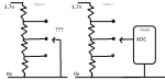
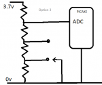
The first PICAXE chips were only 4-bit and the top 30% or so always reported as maximum. That was years ago and every PICAXE since has been at least 8-bit and able to read a pot from 0V to V+.from what I have read about picaxe adc inputs , the picaxes ignore the input voltage between 3.7 volts and 5 volts, and thus the pull up resistor from the 5 volt rail to the 3.7 volt point ,
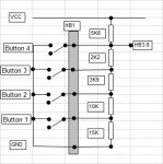
I am surprised you got that high, though maybe it is just because I never managed more than about 4 or 5,, but I never put much effort into choosing suitable resistor values.I have gone further, using a similar technique for a binary encoder switch, but 10 inputs was right on the limit for that one.
I have never been clear on that, had thought the same, but I have seen it described as purely 'a current injection adder' and suggestions it can be used for button push detection., but admit I don't know if that required change-over buttons.My understanding is that the inputs to the R2R ladder need to be at either V+ or Ov, representing '1' or '0'. This would need changeover (1P2W) reed relays.
The problem with a "ladder" of Reed switches operated by a moving magnet is that ideally, either progressively more reeds should close (without any opening), or when each reed closes, the previous should open. But neither of these is easy to achieve, typically a few (or no) reeds will be closed for any particular magnet position. None closed is probably the worst situation because the ADC/PICaxe then needs to "remember" which was the last closed reed. Where more than one reed is closed, then the configuration described by Peter solves the problem because any closed reeds lower down the resistor ladder will be ignored (because there is no voltage across them)......Grounding one of the inputs will change the current thru the resistor ladder thus the voltage to the adc, and its these differences in voltages compared to which input is grounded, is how I want the picaxe to give different outputs.. Its for a water level gauge on a water tank, where a single circular ring magnet floats up and down around a plastic or aluminium tube, that houses reed switches that react to the magnet on the outside of the vertical tube.. Only one resistor will be grounded at any one time..one side of each reed switch will be grounded..
Wired as a pot with the reed relays being the wiper ... ?A simple string of resistors will provide an ADC value which translates simply into % level
 .--------------- 5V
.|.
|_|     \
 }----O O---.---> ADC
.|.         |
|_|    \    |
 }----O O---{
.|.         |
|_|    \    |
 }----O O---'
.|.
|_|
 `-------------- 0V