adc resolution on picaxes, down to 100mV

peter howarth

New Member
Is it possible to program any of the picaxe micros :adc: down to as little as 50 millivolt levels ie the picaxe gives a different output for every step level change of 50mv either up or down..?
 

Goeytex

Senior Member
Picaxe chips can have an ADC resolution of up to 10-Bits. If the reference voltage is 4.096 that is 4 millivolts per step over the range of 0 to 4.095 volts.

Perhaps word your question in a different manner as it is unclear to me as to what you are trying to acomplish
 

hippy

Technical Support
Staff member
Even with the standard 8-bit READADC each step would be about 20mV with a 5V supply so distinguishing 50mV steps should be easy.
 

rq3

Senior Member
Is it possible to program any of the picaxe micros :adc: down to as little as 50 millivolt levels ie the picaxe gives a different output for every step level change of 50mv either up or down..?
Years ago I delved deeply into why the manufacturer of the base chip said not to do this, and never got a satisfactory answer. However, there is an errata sheet that says if you DO use a lower internal reference voltage, you should "step in to it", rather than invoke it in one fell swoop. Using the internal 1.024 volt reference lets you discriminate 1 millivolt per step on a 10 bit ADC like those in the Picaxes, like this:

Code:
init:
setfreq M32                    ;run at 32 MHz
adcsetup=%00010                ;make C.1 ADC input
adcconfig %011                 ;use internal reference and circuit ground
fvrsetup FVR4096               ;step references per Microchip errata sheet
fvrsetup FVR2048        
fvrsetup FVR1024               ;use internal 1.024 volt reference
I've done this on dozens of circuits, and never had a problem.
 

peter howarth

New Member
Thankyou rq3, can I have a 50mv resolution without going to a 32 mhz resonating rock, like can I just go with the internal resonator and still get as low as 50mv distinguisable steps, like I want to have a clockspring type arrangement that uses switches to ground out a series string of 100 ohms resistors, say a dozen, from ground to 3.7 volts supply, to input different voltage to the adc depending which resistor is shunted to ground..
 

Buzby

Senior Member
I'm unclear as to how your circuit is going to be wired.

If you are shorting to ground ( Option 1 ), where do you connect the adc pin ?.
The voltage at the selector will always be 0v, no matter which resistor it is connected to.

Do you mean a circuit like Option 2, which will give a different voltage at each selection ?.


picaxe_adc.png
 

Buzby

Senior Member
I've just thought of another way. Option 3 will work, but it's not as simple to program as Option 2.

picaxe_adc3.png
 

peter howarth

New Member
thankyou buzby, option 3 is what I intend to do, from what I have read about picaxe adc inputs , the picaxes ignore the input voltage between 3.7 volts and 5 volts, and thus the pull up resistor from the 5 volt rail to the 3.7 volt point , will be constant, probably 1kohm for this design..Grounding one of the inputs will change the current thru the resistor ladder thus the voltage to the adc, and its these differences in voltages compared to which input is grounded, is how I want the picaxe to give different outputs.. Its for a water level gauge on a water tank, where a single circular ring magnet floats up and down around a plastic or aluminium tube, that houses reed switches that react to the magnet on the outside of the vertical tube.. Only one resistor will be grounded at any one time..one side of each reed switch will be grounded..
 

hippy

Technical Support
Staff member
from what I have read about picaxe adc inputs , the picaxes ignore the input voltage between 3.7 volts and 5 volts, and thus the pull up resistor from the 5 volt rail to the 3.7 volt point ,
The first PICAXE chips were only 4-bit and the top 30% or so always reported as maximum. That was years ago and every PICAXE since has been at least 8-bit and able to read a pot from 0V to V+.

Any resistor divider will have a maximum simply because there is a 'top resistor' and the trick is to minimise that.

It is possible to have a resistor chain and buttons or reed relays to short resistor nodes to 0V or to short out individual resistors in the chain but it can become difficult to select appropriate resistors and get that working reliably with more than a few buttons. I believe an 'R2R' ladder is recommended in those circumstances.
 

Buzby

Senior Member
I'm not sure the 'R2R ladder' is applicable in this case. My understanding is that the inputs to the R2R ladder need to be at either V+ or Ov, representing '1' or '0'. This would need changeover (1P2W) reed relays.

The mechanical description ( a floating magnet triggering simple reeds indvidually ) looks like Option 2, a tapped string, is the best option. This gives the best range of values per reed, and each step is the same size.

Option 3 ( shorting to ground ) gives a reduced 'full scale', and the interval between each step is not constant.

It is unclear why the OP needs to use Option 3.
 

Aries

New Member
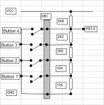
I designed this for my first ever Picaxe project - a rainwater harvesting controller, with four buttons. It gives a reasonably consistent spacing of ADC values (0,71,133,190 and 217 with no button pressed). I have gone further, using a similar technique for a binary encoder switch, but 10 inputs was right on the limit for that one.

25713
 

hippy

Technical Support
Staff member
I have gone further, using a similar technique for a binary encoder switch, but 10 inputs was right on the limit for that one.
I am surprised you got that high, though maybe it is just because I never managed more than about 4 or 5,, but I never put much effort into choosing suitable resistor values.

The problem is, as seen above, the top resistor needs to be quite small compared to the bottom, and another at either end will be a lot lower or higher. That makes it hard to choose resistor values which allow all voltages to be disparate enough to have buttons uniquely identified, or so it seemed to me.

My understanding is that the inputs to the R2R ladder need to be at either V+ or Ov, representing '1' or '0'. This would need changeover (1P2W) reed relays.
I have never been clear on that, had thought the same, but I have seen it described as purely 'a current injection adder' and suggestions it can be used for button push detection., but admit I don't know if that required change-over buttons.

I have never used one, never tried it, and, if it is binary weighted, that suggests a maximum of 8-bit or 10-bit, possibly fewer in practice, and the same limitation to the number of buttons.

There are examples of using a single ADC to read a matrix keypad with quite a few buttons so that might be another option. It would mean a lot more jumper wires for column and row in the sensor assembly than a simple chained resistor ladder.

Of course, multiple ADC could be used with fewer buttons on each.

Added : Or, as it's only detecting if a reed relay is open or closed, create a purely digital keypad matrix and not have to worry about analogue or resistor complexities..

It might make sense to dedicate a PICAXE to such a matrix, have it produce a 'which relay last closed' output for another PICAXE to use. It perhaps depends on what that PICAXE has to do, how much I/O it requires.
 
Last edited:

Buzby

Senior Member
Using 'R2R' for a keyboard is a simple way of handling two buttons at once. The 'R2R' encodes each input in a binary-weighted manner, so the voltage out is the sum of the individual weighted bits.

For example, if the inputs are weighted 1,2,4,8,16, then an output of 6 means the 2nd and 3rd buttons are both pressed. In fact, every combination of buttons will generate a unique output.

A keyboard with 8 buttons could generate 256 different values, 10 buttons would generate 1024 values.

The problem is obvious. As the number of bits goes up, the required resolution gets more difficult to resolve.

The 'R2R' technique was used a lot in D-to-A circuits, to generate analogue signals for audio etc., at the end of the digital stream.

( The outputs of PICAXE are good for driving R2R, because they swing almost rail-to-rail. I've built simple 6 and 8 bit D-to-A this way. )

Anyway, if the project was mine, I'd just use a string of same-value resistors with the reeds connecting to the analogue input of the PICAXE, Option 2.
 

AllyCat

Senior Member
Hi,

Yes, normally an R - 2R ladder is used with Gnd/Vcc input switching to give a full-range output swing and probably good linearity of the DAC. However, this thread appears to have drifted away from Peter's original aim :
.....Grounding one of the inputs will change the current thru the resistor ladder thus the voltage to the adc, and its these differences in voltages compared to which input is grounded, is how I want the picaxe to give different outputs.. Its for a water level gauge on a water tank, where a single circular ring magnet floats up and down around a plastic or aluminium tube, that houses reed switches that react to the magnet on the outside of the vertical tube.. Only one resistor will be grounded at any one time..one side of each reed switch will be grounded..
The problem with a "ladder" of Reed switches operated by a moving magnet is that ideally, either progressively more reeds should close (without any opening), or when each reed closes, the previous should open. But neither of these is easy to achieve, typically a few (or no) reeds will be closed for any particular magnet position. None closed is probably the worst situation because the ADC/PICaxe then needs to "remember" which was the last closed reed. Where more than one reed is closed, then the configuration described by Peter solves the problem because any closed reeds lower down the resistor ladder will be ignored (because there is no voltage across them).

A well-known weather station system arranges that either one or two reeds are always closed at each position of its wind direction vane. Eight reeds radiate out from its central axis with an offset magnet of sufficient strength that it activates either one or two reeds at every wind direction. Thus it is possible to resolve 16 positions with only 8 reeds.

Their particular system uses 8 binary weighted resistors (i.e. 1k , 2k ,4k .... 128k) driving an ADC but this is not an optimum design because never more than two reeds will be closed at any time. Also, with the circular sequence of positions, it would be difficult to reliably distinguish 1k from 1k in parallel with 128k, so the sequence of values needs to be rearranged to run up/down and then a lookup table is used to distinguish the 16 angles.

Cheers, Alan.
 

Buzby

Senior Member
I agree that with the 'shorting to ground' method there is no need to remember the last known value. But the downside is that the values returned are (a) not consistent with level, and (b) don't use all the available ADC range. This means the code is more complex, as it will need tailored lookup tables to convert ADC to % level. ( The inconsistent values and restricted range can be avoided by careful calculation of the resistors, but that's a pain. )

A simple string of resistors will provide an ADC value which translates simply into % level, and if the vessel is straight-sided, easy to convert to gallons, or whatever. If the vessel is tapered, then a lookup table will be needed to convert level to volume. This lookup could be avoided by even more complicated resistor calculations, but the solution would be difficult to calibrate, and would not be easy for others to adapt.
 

hippy

Technical Support
Staff member
A simple string of resistors will provide an ADC value which translates simply into % level
Wired as a pot with the reed relays being the wiper ... ?
Code:
 .--------------- 5V
.|.
|_|     \
 }----O O---.---> ADC
.|.         |
|_|    \    |
 }----O O---{
.|.         |
|_|    \    |
 }----O O---'
.|.
|_|
 `-------------- 0V
 

AllyCat

Senior Member
Hi,

But only if exactly one reed is closed at any time! However, magnetic reed switches don't all have an identical sensitivity and there is very little interaction between them to cause one to drop out when another activates. So a group is very unlikely to behave like (say) a rotary switch or a bilateral multiplexer.

The wind vane that I described above rarely gives EQUAL odd and even- numbered steps, but it does solve the basic problem of zero (or 3+) reeds being activated at any time.

It might be possible to use "change-over" type reed switches, which contain two magnetic reeds (Normally Open) plus one non-magnetic reed (Normally Closed contact), but they are much less common.

Cheers, Alan.
 
Last edited:

hippy

Technical Support
Staff member
I guess multiple closures depends how far apart the relays are. It would be interesting how much difference in voltage there is if one or two adjacent relays are closed. I haven't calculated that but wouldn't have thought shorting out one or two would cause much change if there were enough of them to start with.
 

peter howarth

New Member
I would like to use a potentiometer, but then converting a vertical mechanical rise and fall to a rotating clockwise and anticlockwise shaft is even more challenging than a magnet in a float..Ultrasonics isnt easy either.. I am also trying to make a water level indicator in a mobile tank environment, a tank on a block of land is a whole lot easier than a moving tank of water..
 

papaof2

Senior Member
Depending on the size and shape of the tank, use multiple sensors (maybe ultrasonic?) and average the readings. The average of at most 5 sensors (center, north, east, south, west) should be close to the actual water level.
Not simple or cheap, but likely to be more accurate than other methods.
 

Buzby

Senior Member
Your magnet float idea definitely seems the simplest solution, not much to go wrong mechanically !.
I still think a simple string of resistors from 0v to 5v, with the reeds connected to the ADC input, is the easiest to implement in software.

Let's get the stationary tank sorted first, then move on to the mobile.

Cheers,

Buzby
 
Top