terrapinlogo
Member
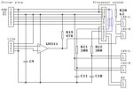
I found a cybot hidden in a box the other day and have pulled it out in hope of converting it to picaxe control. I am trying to use the original light io board to read the ldr's. The board charges a capacitor via the ldr, the micro then measures how long it takes to charge. I have hooked it all up and am currently debuging the code but i seem to be just getting random values.
Schematic
Schematic
Code:
main:

low c.2
pause 100
w0=0
let dirsC = %00000000
time:
pauseus 1
w0=w0+1
if pinc.2 = 1 then value
goto time
value:
debug
pause 1000
goto main