ADC , electric input pulse counter, help please

JPU

Senior Member
Hi All

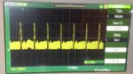
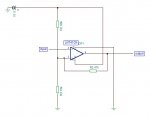
I have been working on a heart pulse counter. I have now created the analogue side and my scope shows quite a nice signal.

Here is the video: http://youtu.be/Z7zFy16563U

I now wish to use the readadc command to count the beats per minute. I have given this some thought and its giving me a little headache as I'm struggling to work out how can I count the pulses received above 2V and then calculate the Beats per minute. I realise I have to count the beats over, lets say a 10 sec period and multiply by 6 to get the BPM but how do I count over a 10 second period. I think I am a little lost as how I can guarantee the time to be exactly 10secs.


Any help or pointers would be appreciated.

Thanks

JPU
 

JPU

Senior Member
Hi

Thanks, I have taken a quick look at the count command. Won't that command count every single pulse. The signal contains many thousands of small signals but only 1 over 2V which is the signal I wish to count.

Can I still use the count command, is there away to eliminate the count of all the other spikes?

JPU
 

MPep

Senior Member
In that case, you may need an amplifying circuit with a level slicer, to remove the lower 'noise' (unwanted signals).
 

JPU

Senior Member
Hi Mpep

That is why I want to use the readadc command as it will be easy to set it to only count pulses above a certain voltage. Its the timings I am having difficulty with. Perhaps it can't be done...any help appreciated.

Thanks
 

Dippy

Moderator
It'll count every single pulse that transits the TT/ST threshold.
Often, in life, you have to process a signal before measuring.

If you can keep the low level noise below the thresholds (and the genuine signal above the levels) then it should be OK.
You could add filtering and use comparators to 'square' up the pulse specifically for the PIC input.
Or use the PIC comparators with a change of code.
It shouldn't be too difficult.
 

Buzby

Senior Member
Which PICAXE is it ?

Some chips have an analogue comparator built in, this may make your task easier.
 

Jeremy Harris

Senior Member
Another approach might be to digitally filter the ADC data. If you sample at a rate that's a fair bit faster than the maximum heartbeat (say, around 50 to 100 times per second) then you should end up with a digital representation of the signal you can see on the 'scope. You can then either set fixed or variable (maybe differential) thresholds or even do some proper digital filtering to get the wanted peak signals from the noise.

I suspect this will give you a more reliable signal than using a comparator, as you can incorporate dynamic filtering to, in effect, alter the filter time constant on the fly, if need be.
 

JPU

Senior Member
Hi Buzby

I don't mind which picaxe I use. I would prefer to use the 08m2 for the sake of testing but I have a 14m2 here and 18m2.

Dippy, Thanks for your post, that all sounds complicated to me!

JPU
 

MFB

Senior Member
If you count pulses on a Schmitt (ST) the only signal conditioning circuitry that you might need is a series resistor with a capacitor between the ST input and ground. Try a few tens of K Ohm and a 0.1uF to start with and adjust the values for best results on your signal using a scope.
 

JPU

Senior Member
Hi MFB

That looks like something I could work with. In essence do you mean I should run my analogue circuit output that is currently seen on the scope through a Schmitt trigger. I will then only produce a pulse when the trigger goes high, lets say 1.5V??? I think this is what you mean??? or if not will this work??

Then I could use the count command to count the pulses??

Just
 

Dippy

Moderator
Imagine a threshold switch with 2 thresholds. I know that sounds silly.
When the signal is higher than the 'high' threshold - O/P=High.
Then, when the signal goes lower than the 'low' threshold - O/P=Low
(edit: when I say O/P=... I mean thats how an external device would work and it's also how an IF port.pin would see it too).

The PIC inputs are like this, though the threshold levels depend on whether the PIC input is TTL or Schmitt Trigger.
So, success could be as simple as suggested by MFB or a pot or a pot plus a little RC filter to remove noise.
You may not need any external ICs.
It's worth a play and a little drop of code in a loop testing the PICAXE inputs.

Have a read of PIC data sheets (they're long) to check actual values.
Time consuming... but worth it for this and future projects.
 

AllyCat

Senior Member
but only 1 over 2V which is the signal I wish to count.
Hi,

The swing required by a ST input is probably too large. There are various possible methods using different levels of hardware versus software complexity:

I believe that comparators are supported in PICaxe Basic on X2 devices, but most/all chips have them. However, (on M2 chips) it requires "advanced" programming techquiques (peek/poke SFRs , etc.) which are not easy or quick to use.

The simplest method is probably to ac (capacitor) couple the "pulse" to a digital (not ST) input and bias the pin (via a resistor) from the D/A converter output pin** (a buffer is recommended but might not be essential). Use the PULSIN command to read the width of the mark (pulse width) and space* (gap between) as a "sanity check" that the level is correct (and adjust the D/A output to correct any errors). Add the mark and space values to give the period (maybe average for several cycles) and then divide 60,000 by the period in ms) to give the frequency (pulse rate).

* The "space" is probably over the maximum 655ms period, so either use PULSIN's timeout facility or drop the clock temporarily to 2 or 1 MHz (SETFREQ).

**EDIT: Sadly the D/A output is not conveniently accessible on some PICaxes (but it can be internally connected to a comparator input) so you may need to just use a pot across the rails.

Cheers, Alan.
 

JPU

Senior Member
Hi All

Thanks for your inputs, sadly most of your suggestions are way over my skill level. Alan, yours is very detailed but is way over my head.

I am trying to keep this as simple as possible and I have a suggestion which maybe some of you can let me know if its a way to go or forget it..

Idea---->

I will measure the voltage with readADC. I will use the reference voltage of 3V which is powering the picaxe. When the readadc value is higher than 100 (I havent worked out the exact value need but you know what I mean, Im sure) I could use an interrupt command to start a count. This will continue for 10seconds. Each time the readadc receives the +100 signal I will create another new interupt which will increment a variable by +1. This will all end when the 10 seconds is up. Multiply the result by 6 and bingo,,,result..

Is this idea? possible or is this in a perfect world??

Please can you point out any hidden obstacles here that may crop up or is it just not feasible.

Thanks

JPU
 

Buzby

Senior Member
Hi JPU,

No need to complicate things with interrupts.

Read ADC
Is > 100 ?
No - Go back and read again
Yes -
Was the previous reading > 100 ?
Yes - we must still be in the pulse, go back and read again
No - this is a new pulse, increment count, go back and read again

Wrap a test of the TIME around this and you have the core of your heart rate monitor.

Cheers,

Buzby
 

AllyCat

Senior Member
Hi,

Yes, sorry, I did give a very brief summary of how I (as primarily a hardware engineer) would tackle the problem.

However, I do suggest that you seriously look at using the period between pulses, not a count. If you measure over 10 seconds then the heart rate can only be calculated in increments of 6 (e.g. 72, 78, 84, etc. bpm). It's almost the same issue as in a couple of motor cycle speedometer threads a few weeks ago where it was realised that it is much better to measure the time taken for one revolution of the wheel, not the number of revolutions in a fixed time.

And as Buzby says, don't try to use interrupts.

Cheers, Alan.
 

Buzby

Senior Member
... look at using the period between pulses, not a count ...
Hi Alan,

Exactly, but I thought we'd get JPU counting pulses accurately before moving on to the slightly more complex duration measurements.

Cheers,

Buzby
 

jedynakiewicz

Senior Member
If you are trying to filter out and measure peak voltages only, why not use a simple voltage-divider arrangement with two resistors? Select a voltage-divider ratio that will give you a level that will trigger an input but the lower level noise will not. The very useful PICAXE Command Calculator 1.11 has a Potential Divider Wizard that will calculate the resistor values for you. That way, you don't need to fiddle around with ADC's or suchlike. I am assuming that there is a fairly decent ratio between the voltage peak that you are trying to use and the underlying noise.

You can get the PICAXE Command Calculator from this website (http://www.picaxeforum.co.uk/attachment.php?attachmentid=12015&d=1345298285)
Also, look at the INPUTTYPE command in Manual 2 for details of the voltage levels that trigger the inputs for each chip type, the pins upon which ST or TTL are available and how to select them.
 

Buzby

Senior Member
Looking at the video JDU posted I'd say he's already got a good analogue circuit in place already.

All he needs now is some software to count the peaks. It may need some scaling to accommodate varying pulse levels, but I'm sure this can all be done in software.

The first thing is to detect the pulses accurately, don't worry about counting or timing yet.

A simple 'beep' for each pulse will do for now.
 

JPU

Senior Member
Hi Guys

Thanks for your ideas, this is slowly starting to make a little sense to me. Buzby, I like your approach, Hippy advised me in another thread to break down the problem so as to make the approach easier and it worked.

I can see how counting the space between pulses is the way to go. So can you guys help me along this path..


Idea---->

Use a picaxe using the readadc command to sense when the peak occurs and ends.
Start a timer which counts until the next readadc value goes high (100+) again. (stop timer)
divide 60 by the count, the result is the BPM

This sounds good but problem I see is If I program the pick to readadc until the input goes 100+. I will then wait until the peak ends, ie<100 before I start the timer. How do I then instruct the counter to count in a recognised or time interval equivalent until the next peak.

I have come up with this simple idea but the problem is how do I work out what the time equivalent of the count variable is in my program (is there a way?), How long does it take for the subroutine jumpout to loop. If I know this I will know the value of count as a time interval. Should I introduce a pause???

(please forgive me syntax, I fiddled with BASIC 25years ago. I know that I will have to revise the instructions for picaxe but you guys will know what I mean)


start:
readadc
If readadc>100 then readvalue=1
else readvalue=0
if readvalue=1 then goto jumpout
goto start

jumpout:
let count=count+1
if readadc>100 then goto clockstopped
goto jumpout

clockstopped:
let bpm=60/count
print bpm

end:

Thanks for taking the time to help.

JPU (Justin)
 

Buzby

Senior Member
Hi Justin,

First let's flash a LED every time we detect a pulse.

do
Detect a pulse
Turn on LED
Pause a little
Turn off LED
loop

Get this code running, then post it here.

Then we'll move on to timing, counting, trending, alarming etc. etc.

Don't try to run before you can walk, you'll strain your heart ( and brain ! ) :)

Cheers,

Buzby
 

AllyCat

Senior Member
Hi Justin,

One of the problems is that PICaxe commands don't execute in a completely constant or predictable time. However, your idea can be simplified to the following with reasonable results:
Code:
symbol cnt = w2
symbol adc = b1
symbol inp = c.1

main:
	readadc inp,adc
	If adc <= 100 then goto main
	let cnt = 0
start:
	readadc inp,adc
	let cnt = cnt + 1
	If adc > 100 then goto start
jumpout:
Note that count is a reserved word, start is ok but start1 etc. are also reserved. It's then fairly easy to modify the code to read between two consecutive rising (or falling) edges. Beware that PICaxe only handles integer maths, so you will need a calculation nearer to let bpm = 20000 / cnt .

The "normal" way to measure instruction timings is by counting the number of loops in a specific time (or time for a number of loops) using a stopwatch or the internal time variable (seconds), for example:

Code:
	do : loop until time > 0    ; wait until time = 1 second
	do
; code under test
	loop until time > 10   ; fall through when time = 11 seconds
For alternative methods and typical execution times see this thread (which is probably rather more than you want).

However, as I mentioned in #13, it's far better to use the "proper" PICaxe commands to measure time periods. But there are a few "gotchas" so let's leave that for now.

I see Busby has beaten me with some good advice, but I'll post this now anyway, as I'd already written most of it.

Cheers, Alan.
 

MFB

Senior Member
boriz: Yes that was what I suggested way back. Its an approach that could have been knocked up and tested very quickly. Like others have suggested, with simple code to look at a PICAXE ST input and flash a LED to show when its triggered. Probably one of those cases of try it, not much time wasted if it does not work.
 

AllyCat

Senior Member
thousands of small signals but only 1 over 2V which is the signal I wish to count.
Hi,

IMHO it would have been better if the OP had posted a "still" photo rather than (or as well as) a video. Then, it can be seen that the waveform peak is only 1.5 volts (so the required threshold is about 1 volt) not the 2 volts which was requested. :confused:

Heartbeats.jpg

Certainly an R-C (low pass) filter would help to kill the "grass" at the bottom (I guess the "jaggies" on the edges are digital sampling artefacts), but a standard PIC digital input (not ST) should detect the pulse (if as shown in the video/photo) well enough. Strictly, the "Min High" (D040) is a little high (at least if the supply rail is the normal 4.5 - 5.0 volts, which we haven't been told), but will probably work fine in practice. If the supply rail is less than 4.5 volts (or the waveform is actually larger than the 'scope calibration), then the "grass" might indeed be an issue.

PICinputdata.png

But IMHO a simple ac coupling with an adjustable/auto input bias should be all that's required.

Cheers, Alan.
 

Goeytex

Senior Member
Either of the two attached circuits should work fine. One uses a an LM393 comparator and the other uses a LM358 Op Amp as a buffer and a comparator.

The pot adjusts the trigger threshold. Simply adjust the pot until the output pulse is nice and clean. I would initially adjust the pot for 3. volts at the center tap.

Good Luck
 

Attachments

MFB

Senior Member
Any form of comparator without positive feedback to give hysteresis is likely to generate multiple output pulses for each input transition. In addition to hysteresis, an RC low-pass filter at the comparator (or ST) input should be used to reduce the noise bandwidth.
 

Goeytex

Senior Member
Any form of comparator without positive feedback to give hysteresis is likely to generate multiple output pulses for each input transition. In addition to hysteresis, an RC low-pass filter at the comparator (or ST) input should be used to reduce the noise bandwidth.
Not universally true. Both of these have such a slow response that they should work fine as drawn. I might agree if I had used an LM311.
In any case should multiple pulses or ringing be seen, feedback can be easily added with a couple of resistors. Personally, I wouldn't bother with a low pass filter, unless in-circuit testing indicates an actual need. I generally prefer to taste my steak before adding more salt.
 

JPU

Senior Member
Hi

Thanks for your replies.

I have spent the day working on the a Schmitt trigger to try and produce a stronger signal. I have included an image of the schematic. Although there is now a definite pulse in the output, today I have been struggling to achieve a clear signal from the original circuit which I have also included an image. I will have another go tomorrow using the suggestions made by Goeytex (thanks) but I will also have to improve on the signal capture / amplification part of the circuit before I think I can proceed.

Please note, I have purchased Skintact electrodes to replace the coin electrodes and the input to the ST comes from pin 7 of the LM358, I have also been advised to change the LM358 for OPA134 as they are less noisy.

Thanks all for your help so far.
 

Attachments

Buzby

Senior Member
Hi Justin,

I'm not an analogue guru, so I can't comment on most of what is being discussed about filters and feedback.

But I can see that way back in post #1 you put up a video of a waveform that even the simplest micro with an A-to-D could handle.

Have you tried putting your signal into a PICAXE yet ?.

If you can get a signal that looks as good as post #1 into the PICAXE then the rest of the work is a just few hours coding.

Cheers,

Buzby
 

JPU

Senior Member
Hi Buzby

No I haven't tried yet. I have got a little lost with trying to improve/make the signal clearer.... I think your right and I should have just had a go with the code to see what happens. I will crack on with getting some coding done and let you know what the results are like.

As you suggested in post #21 I will just get a light to come on first(using a picaxe) to represent the beat and go from there...

Thanks

Justin
 

AllyCat

Senior Member
I will also have to improve on the signal capture / amplification part of the circuit before I think I can proceed.
Hi Justin,

Yes, I'm surprised you can get any consistent results at all. A quick Google suggests that the signal should be about 1mV, so a gain of a few thousand is required. However, you have a theoretical low frequency gain of 1,000 in the first stage and 100 in the second (totalling 100,000), both non-inverted. So I'm surprised it's stable (or perhaps it isn't and your issue is instability not "noise"), particularly as I see no supply decoupling capacitor shown on the Op-Amp. However, the capacitors in the feedback loop are so large that the bandwidth is only a few Hz (so amplifier noise shouldn't be an issue), which is perhaps why the pulse is not as "sharp" as might be expected.

But my main concern is that the amplifier stages are biassed with both their outputs nominally at zero potential (but dependent on their unknown input offset voltage). I've never tried monitoring heart signals (and wonder if a microphone might be a safer option) but I would probably start with an inverting gain of about 100 in the first stage, with output biassed at about Vcc/2 and a gain of 20 - 50 in the second stage, possibly with the output biassed a few hundred mV above ground.

I doubt if a Schmitt Trigger circuit is required at all, but if so, I'd use an adjustable threshold but a hysteresis smaller than 1 volt. However, as Goeytex says, even a PICaxe should be able to perform the waveform detection directly from the Op-amp, unaided.

Cheers, Alan.
 

John West

Senior Member
The R component is fine for counting, but P, Q, S and T are pretty much buried either by noise or some low level oscillation. I think the software fix would be easier if you first cleaned up the incoming waveform.

Do you use a conductive gel, or some such beneath your "coin" electrodes? That might boost the signal a bit, in and of itself. It's always easiest to get good data from a good signal.
 

boriz

Senior Member
"I think the software fix would be easier if you first cleaned up the incoming waveform. "

And we're back to the simple RC low-pass filter. A single capacitor and a single resistor, then the rest done in code. Should be a breeze.
 

JPU

Senior Member
Hi Guys

Sorry for the delay. I have taken all your advice and I worked on the signal capture circuit and also learned a little about filters. I have improved the signal and managed to get rid of quite allot of noise. I am now left with a strong peak in the wave that occurs with each heart beat. The sensors are also much more reliable and I am able to achieve a good signal easily.

I have attached a link to the youtube movie for you to see and the code is below. As Buzby suggested I have just tried to get the picaxe to detect when the signal occurs. It all seams to work fine so I am on to the next step. I need to now count the beats over a 5 second period and if anyone can help me with that or just some ideas I would be grateful.

To sum up the video and circuit.

There are three LEDs. One is connected to the sensor circuit that flashes with every heart beat. The bottom two LEDS flash in response to detecting or not detecting the incoming pulse from the sensor circuit. So the top circuit is the op amp OPA134 and the bottom circuit is the Picaxe. I hope you can understand my gibberish!

I'm sorry about the mess on the table, not very professional, I know!

Thanks

Justin

Video: http://youtu.be/WlcPVGRN298

Code:
'simple program to test the adc using readadc on c.4 if the input <100 
'then no beat detected, if >100 then beat detected.


' === Constants ===
	symbol  low_LED = 1					' LED on output 1 (pin 5) 
	symbol  high_LED = 2					' LED on output 2 (pin 6) 
	
' === Variables ===

	symbol ADCval = b5					' used to store ADC value
	

' === Directives ===
   									
   #picaxe 08M2							' specify processor
   #terminal 2400							' open terminal window

' =================== Begin Main Program ====================


' ++++   Simple flash of the LEDs to ensure that the LEDs are ok and the Picaxe is on ++++
	high high_LED
	pause 1000
	high low_LED
	pause 1000
	low high_LED
	pause 1000
	low low_led
' ++++End of LED test patterm +++++

do
									
	readadc c.4,ADCval					' get ADC value
	
	if adcval>100 then high high_LED: low low_led	' if the heart beats then the readadc is >100 light high_LED
	end if
	
	if adcval <100 then high low_LED: low high_led	'if no beat detected then readadc is <100 light low_led
	end if
	
loop
 

hippy

Ex-Staff (retired)
Given you are pulsing the LED on an ADC reading, and selecting on a level of 100 ... That's just below half of supply so I'd guess around 2V which should be enough to detect with a digital (TTL) input. If you can get that working then you have easy access to COUNT and PULSIN commands plus interrupts and timer tricks which can be driven by digital signals.
 

Buzby

Senior Member
I'd stick with ADC, not TTL, it gives you more flexibility if you need to tweak sensitivity levels.
 

JPU

Senior Member
I'm a bit of a new comer to the terminology. Is TTL transistor to transistor logic? If thats the case then I will go off and read about it.

As with whether or not to use TTL or ADC, can I assume that I can't use the count command with ADC and only if I use the TTL format. If that is the case then am I correct in thinking that using TTL means I need a signal to be 2V+, to be reliable? If this is the case then I can see why ADC may be a better choice as 2V+ will only be guaranteed from my circuit if the electrodes are placed well. I always get a pulse but the Voltage is varied due to the strength of input the signal.
 

Buzby

Senior Member
TTL is, as you say, Transistor Transistor Logic. The name comes from the way ICs developed.
For comparison, an earlier generation of ICs used RTL, Resistor Transistor Logic.

Actual TTL has a specific switching voltage range, so when we talk about a PICAXE input being 'TTL' we are only talking about it's switching voltage.

Sticking with analogue gives you the flexibility to adjust the effective switching voltage to whatever you want, and do it 'on the fly'.

You will lose the ability to use COUNT command, but gain so much more flexibility ( and learn a bit more about what a PICAXE can do ) if you stick with analogue.

Cheers,

Buzby

EDIT : Try this :
Code:
#picaxe 08M2

' Hearbeat


' Symbols
Symbol PulseLED 	= 1
Symbol ADCval 	= b5
Symbol TrigLev 	= b6
Symbol PulseCount = b7
Symbol BPM        = b8


' Code starts here

TrigLev = 100

' Main loop, repeats indefinately
do

      ' Reset the timer
      time = 0


      ' Timed loop, repeats every X seconds
	do

		' Find High, Stay in this loop until trigger level reached
		do
			readadc c.4,ADCval 
		loop until ADCval => TrigLev 
		High PulseLED
		
		
		' Stay in this loop until below trigger level 
		do
			readadc c.4,ADCval 
		loop until ADCval < TrigLev 
		Low PulseLED
		
		
		' Now we have seen a pulse, so count it
		
		PulseCount = PulseCount + 1
		

	loop until time => 5 ' End of timed loop

	
	' Calculate BPM
	BPM = 12 * PulseCount	
        debug ' Show result
       
      ' Reset count ready for next measurement
      PulseCount = 0	
	

loop ' End of Main loop
 
Last edited:

boriz

Senior Member
Better to time the intervals between peaks than to count peaks. Much more accurate and faster to update. Though there's no reason why you can't use both methods and average them or something.

This will be a little tricky using ADC, but not impossible.

EG: You could count the number of times around the ADC loop between peaks (nL). This number will then need scaling based upon exactly how long it takes for the Picaxe to execute the loop.

Since you seem to have a cool 'scope, it will be easy to get a good ballpark figure then tweak it if needed. Just toggle a spare output inside the loop and monitor that with your 'scope. It will give you an accurate figure for the duration of a loop (tL). Then tL*nL = the time interval between peaks (tI). Then, assuming you are working in milliseconds, 60000/tI will give you BPM.

Note: The toggle command, although used only once to establish loop duration, will itself effect the reading. So for accuracy you'll have to leave it in.

Just one idea of how to do it using ADC. I'm sure there's others.

Personally, I'd probably use a little more amplification on the analog side to get a nice 5v signal and then use digital timing commands.

P.S. TTL usually just means 5 volt logic.

P.P.S. Your code tests for >100 and for <100. But what about exactly 100? You should change one of those numbers. Say >99 perhaps. Or better still, use only one test and an ELSE.
 
Last edited:
Top