Hello everybody,
As I am eventually trying to use the PICAXE for some climate control (and I am about to place a electronic supply order soon) I would like to know
if my basic thoughts on this issue are right:
Let me explain:
Summary:
Using a variable voltage source (80V AC to 230V AC) to control a fan (100watt; 3 wires => 1 fase) watts. PICAXE controlled relays will switch a different
voltage to the fan depending on the temperature. Solid state might be used to disconnect the fan prior to changing voltage.
So no "sine wave cutting" i read about on this forum.
Some detail:
Hardware:
A fan (LTI if that's of any interest), less then 100 watts runs on mains voltage (230 Volts) has a three wire connection so its 1 phase (and neutral + PE). 100 Watts @ 230 Volts will be well under 1 A of current.
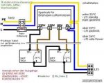
A transformer which supplies a couple of different voltages (80V to 230V), its able to supply well over 1A of current, this is what controls the speed of
the fan. It is especially mentioned on this site this transformer can be used to control LTI vents.
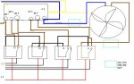
Switcher relays (or do you call em changers? They are called "Wechselrelais" in German); they don't open or close a circuit but alternate between circuits
See drawing for details:
These relays will be controlled by the picaxe, they will change the transformer output voltage the fan is connected to depending on temperatures.
They are "printmontage" type of relay. they can take mains voltage and about 3A of current.
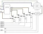
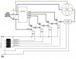
Solid state relay (zero-cross; optically isolated; TTL compatible):
I am not sure if this relay is a smart choice but I am contemplating to use the solid state to switch the fan OFF before switching the switcher relays
(to eliminate back emf and friends caused by the fan interfering with the picaxe side the circuit).
One example sequence would be: (start condidtion fan on)
solid state off (Low0) - pause 100 - switching relays in position (from high 1 to high 1 high 2) - pause 10 - solid state on (high0)
The solid state relay I am aiming for can switch much more than 10 amps ( more like 20 or 30 ish).
The coil circuit of the switching relays will have the appropriate diode to protect the switching circuit (logic side).
I hope I managed to give you an idea of what I am aiming for.
The boxes (cyan) in the drawing are sugested positions for the solid state relay. Only one will be used (I like the idea of cutting the fase to the motor not the neutral... neutral good...fase bad).
Wire colors:
Black/Brown: fase (Black also 5V of logic circuit)
Blue: neutral
Yellow: (should be green/yellow) PE
Red: 0V of logic circuit
I would be grateful for any thoughts on this issue.
My appologies for this lenghty post (again )
)
I will get help to do the mains wiring.
Cheers,
Florian
As I am eventually trying to use the PICAXE for some climate control (and I am about to place a electronic supply order soon) I would like to know
if my basic thoughts on this issue are right:
Let me explain:
Summary:
Using a variable voltage source (80V AC to 230V AC) to control a fan (100watt; 3 wires => 1 fase) watts. PICAXE controlled relays will switch a different
voltage to the fan depending on the temperature. Solid state might be used to disconnect the fan prior to changing voltage.
So no "sine wave cutting" i read about on this forum.
Some detail:
Hardware:
A fan (LTI if that's of any interest), less then 100 watts runs on mains voltage (230 Volts) has a three wire connection so its 1 phase (and neutral + PE). 100 Watts @ 230 Volts will be well under 1 A of current.
A transformer which supplies a couple of different voltages (80V to 230V), its able to supply well over 1A of current, this is what controls the speed of
the fan. It is especially mentioned on this site this transformer can be used to control LTI vents.
Switcher relays (or do you call em changers? They are called "Wechselrelais" in German); they don't open or close a circuit but alternate between circuits
See drawing for details:
These relays will be controlled by the picaxe, they will change the transformer output voltage the fan is connected to depending on temperatures.
They are "printmontage" type of relay. they can take mains voltage and about 3A of current.
Solid state relay (zero-cross; optically isolated; TTL compatible):
I am not sure if this relay is a smart choice but I am contemplating to use the solid state to switch the fan OFF before switching the switcher relays
(to eliminate back emf and friends caused by the fan interfering with the picaxe side the circuit).
One example sequence would be: (start condidtion fan on)
solid state off (Low0) - pause 100 - switching relays in position (from high 1 to high 1 high 2) - pause 10 - solid state on (high0)
The solid state relay I am aiming for can switch much more than 10 amps ( more like 20 or 30 ish).
The coil circuit of the switching relays will have the appropriate diode to protect the switching circuit (logic side).
I hope I managed to give you an idea of what I am aiming for.
The boxes (cyan) in the drawing are sugested positions for the solid state relay. Only one will be used (I like the idea of cutting the fase to the motor not the neutral... neutral good...fase bad).
Wire colors:
Black/Brown: fase (Black also 5V of logic circuit)
Blue: neutral
Yellow: (should be green/yellow) PE
Red: 0V of logic circuit
I would be grateful for any thoughts on this issue.
My appologies for this lenghty post (again
)I will get help to do the mains wiring.
Cheers,
Florian
Attachments
-
 38.1 KB Views: 90