AC motor, controlling with variable voltage

lahaye

Member
Hello everybody,

As I am eventually trying to use the PICAXE for some climate control (and I am about to place a electronic supply order soon) I would like to know
if my basic thoughts on this issue are right:

Let me explain:

Summary:
Using a variable voltage source (80V AC to 230V AC) to control a fan (100watt; 3 wires => 1 fase) watts. PICAXE controlled relays will switch a different
voltage to the fan depending on the temperature. Solid state might be used to disconnect the fan prior to changing voltage.
So no "sine wave cutting" i read about on this forum.


Some detail:
Hardware:

A fan (LTI if that's of any interest), less then 100 watts runs on mains voltage (230 Volts) has a three wire connection so its 1 phase (and neutral + PE). 100 Watts @ 230 Volts will be well under 1 A of current.

A transformer which supplies a couple of different voltages (80V to 230V), its able to supply well over 1A of current, this is what controls the speed of
the fan. It is especially mentioned on this site this transformer can be used to control LTI vents.

Switcher relays (or do you call em changers? They are called "Wechselrelais" in German); they don't open or close a circuit but alternate between circuits
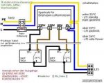
See drawing for details:
These relays will be controlled by the picaxe, they will change the transformer output voltage the fan is connected to depending on temperatures.
They are "printmontage" type of relay. they can take mains voltage and about 3A of current.

Solid state relay (zero-cross; optically isolated; TTL compatible):
I am not sure if this relay is a smart choice but I am contemplating to use the solid state to switch the fan OFF before switching the switcher relays
(to eliminate back emf and friends caused by the fan interfering with the picaxe side the circuit).


One example sequence would be: (start condidtion fan on)
solid state off (Low0) - pause 100 - switching relays in position (from high 1 to high 1 high 2) - pause 10 - solid state on (high0)

The solid state relay I am aiming for can switch much more than 10 amps ( more like 20 or 30 ish).
The coil circuit of the switching relays will have the appropriate diode to protect the switching circuit (logic side).

I hope I managed to give you an idea of what I am aiming for.


The boxes (cyan) in the drawing are sugested positions for the solid state relay. Only one will be used (I like the idea of cutting the fase to the motor not the neutral... neutral good...fase bad).
Wire colors:
Black/Brown: fase (Black also 5V of logic circuit)
Blue: neutral
Yellow: (should be green/yellow) PE
Red: 0V of logic circuit

I would be grateful for any thoughts on this issue.
My appologies for this lenghty post (again:eek:)

I will get help to do the mains wiring.


Cheers,
Florian
 

Attachments

manuka

Senior Member
PICAXE controlled relays will switch a different voltage to the fan depending on the temperature.
So when warmer the fan spins faster & vice versa ? As most home fans have several speed settings anyway ( I've a 230V 35W 3 setting one here) this shouldn't be too difficult, BUT strongly suggest you try the concept out with a 08M/DS18B20 & small DC motor switched by a NPN transistor- maybe even using PWM.

Have you done any PICAXE work before? Although easy to use, I'd highly recommend that you didn't start with them on a mains powered project !

I'm sure you are aware that (climate-wise) warmer conditions may be only part of the need for switching a fan,with humidity highly significant. I personally get annoyed by noisy small fans, & other aspects (like blade pitch, diameter & even placement) influence the amount of air that'll be moved of course. Often more suitable passive approaches could assist- tropical Australians love their cooling "breezeways"- it depends on your actual needs.
 
Last edited:

BCJKiwi

Senior Member
Are you sure about the circuit diagram?

the loop of the neutral to 'off' contact on relays 2,3 & 4 would concern me.

Also what protection do you have against having more than one relay switched at the same time.

This circuit does not begin to approximate a multiposition switch which one would assume you want to emulate.

Not sure what the budget is but you could use a specialised SSR like the CRYDOM 7pcv2415 which is a proportional AC V out in response to a 0-7V DC in which could be derived directly from your temperature sensor.
 
Last edited:

lahaye

Member
Hello down there,

Thank both of you for your replies.

@manuka

I will definitely not start on this project right away, and I would first do the logic part, no mains attached, make sure it works, then add the mains part (under supervision).
Its just I would need to order these parts now, as there is a minimum order value of 150 euros (from Germany to Holland).... and the solid state is 15 euro. It won't be feasible to order it only.

@BCJKiwi


Thank you for pointing me to this part, seems very useful but it does indeed break the bank ... and the datasheet (2 pages) specifically states no AC motors should be used as load with a pcv relay.


About my drawing:
I think there is a misunderstanding, I seem to be very unprecise. My apologies.

Please let me clarify:

First there is no need to prevent multiple relays from being turned on at the same time, this is actually desired. In any case only one voltage will be connected to the fan at any one time (even with all relays on). If I want to connect the fan to 230 V all 4 relays will have to be on at the same time.

The neutral wire is the blue one. It is only connected to the transformer and fan (and maybe the solid state).
The black wire that is looping from relay to relay will have fase on it (up to 230V). So no neutrals connected to relay 1 to relay 4.

The basic idea of this circuit (including a drawing) was put online by someone how claims to be an electrician (and I think he is as he keeps referring to the VDE [German electricians association] regulations; a very responsible thing to do). I added two more relays though.

Lets say relay 1 and 2 are on at the same time:
80 volts won't be connected to the fan anymore (as relay 1 has switched from 80V to relay 2), relay 2 itself is not connected to 110V anymore but to relay 3. Relay 3 is connected to 150 V. So 150 V are now connected to the fan (150V going from transformer into relay 3, via black wire loop to relay 2, via black wire loop to relay 1 and and from there to the fan).

I hope I managed to clarify what the idea of this circuit is.


I am not living in Australia but for me 30 Celsius is VERY hot (dutchies can't stand any temperature thats more than 3 degrees from room temperature ;) )
So if the sun is burning down on the apartment I want to get the heat out.


Cheers
 

kevrus

New Member
I think it would be easier with a PWM circuit firing a triac via a zero crossing opto-isolated triac driver, or a purpose designed solid state switch as BCJKiwi says. Why is there a zero cross switch on the neutral line?
 

BCJKiwi

Senior Member
"First there is no need to prevent multiple relays from being turned on at the same time, this is actually desired. In any case only one voltage will be connected to the fan at any one time (even with all relays on). If I want to connect the fan to 230 V all 4 relays will have to be on at the same time."

From this I assume that the relays are shown in the 'Off' position.

"Lets say relay 1 and 2 are on at the same time:
80 volts won't be connected to the fan anymore (as relay 1 has switched from 80V to relay 2), relay 2 itself is not connected to 110V anymore but to relay 3. Relay 3 is connected to 150 V. So 150 V are now connected to the fan (150V going from transformer into relay 3, via black wire loop to relay 2, via black wire loop to relay 1 and and from there to the fan)."

From this I assume the relays are numbered from 0 at the right to 3 at the left.

Are these assumptions correct? - perhaps the diagram could be labeled.

How are the transformer windings constructed?

It appears a design for something else is being adapted - which is OK provided the system is really the same.

If the relays are in the positions shown then the 80,110,150 & 180V windings are all shorted together - not good if this is a straight forward multi-tap transformer.

Would have assumed that 1 relay would be required for each tap, all wired the same way as the three right hand relays with only one connected to the transformer at a time (what I would have called 'on'). Then safety interlocks would be required to ensure only one is 'on' at any given time, not sure I'd trust the PICAXE for this as incorrect logic/component failure would create a short between windings in the mains transformer - nasty!

With regards to the comment on not using the variable output SSR for AC motors, this is valid for most industrial motors but the motor in this fan is obviously designed for variable voltage.
 
Last edited:

hippy

Technical Support
Staff member
The relay selection looks okay to me and won't cause any shorts but it does illustrate that it's not the best way to draw such a circuit.
 

moxhamj

New Member
Re "I am not living in Australia but for me 30 Celsius is VERY hot".

Hmm, for me 30C is a bit cool for a trip to the beach. I prefer 35C+

And 43C is getting very nice for a swim. I like getting in a hot car when it is 43C outside, then winding down the window and letting the nice cool air blow in!

Re a cooling fan, how much air does this need to move? I'm just wondering about 12V car radiator fans which are relatively cheap and are safe at 12V. Plus you can run them off a mosfet using PWM from a picaxe giving continuously variable speed. Though you might need a big 12V supply or charge up a 12V lead acid battery. Just a thought - I don't know how big these fans are. Maybe you only need smaller fans. Even a computer fan can move a lot of air. But please ignore this suggestion if you have already ordered parts. I'm sure what you are building will work fine too.
 
Last edited:

lahaye

Member
A Good day to all of you,

I had written a lengthy response, then I saw BCJKiwi's reply and was pretty much back to start then IE crashed and the situation had changed again...:)
Well after hearing there were short circuits I immediately began to see lots of them, then I contemplated this a bit an then I saw no short circuits again... somehow pretty funny, as long at this is in the theoretical stage.

I think I can clarify this setup by posting the original circuit drawing (it only uses two relays) which is much better than mine. My apologies for the badly labeled drawing and thanks to all who have bothered taking a good look at it anyway.
This one is not a logic circuit control so there are some kind of (fridge-tech bi-metall based?) thermostats that can be set at different temperatures. They cost 20 euros a piece, you can't play with them as with a logic based control and they need to be wired up as well (no sidestepping the mains voltage connection issue) so: no thank you. But the circuit looks nice. The designer specifically mentions NOT to connect voltage outputs together.


Lots of thanks to BCJKiwi for clarifying the DONT statement from the 7pc2415 datasheet concerning the use in connection with AC motors, If I can find a supplier in the EU I guess I'll be set.

There are 2 concerns I have though:
a)
It is stated that when using a Dimmer to regulate Fan speed a irritating noise (humming) is generated. This is not the case when using the voltage supply which is used in the circuit attached to this post.
I don't know if the 7pvc2415 can be compared to any of the above.
b)
The supply voltage needs to be up to 7 Volt but I guess a simple Op-Amp (non-inverting) circuit would be sufficient to boost the PICAXE output voltage to 7/5 of Vsupply (=7 Volts).
Also a circuit which outputs a analog signal (output voltage from 0V to 7 V pre Op-Amp). I am sure plenty of information can be found on this site concerning this issue.


Concerning my own drawing:
Yes the relays are numered 4 to 1 from left to right, the state they are shown in is the off state. I am not sure what kind of transformer it is but the different fase output are defenetly not allowed to be shortend together. It is defenetly not intended also.


Concerning the choice of equipment:
I think I will need quite some power, as I prefer not to run it at max RPM for noise reasons, at least most of the time. Also the fact that there probably will be some ducting (= higher Impedance, airflow impendance that is) involved raises the requirements for Fan capabilitys.

Concerning Beach tempertures:
For the Beach 30 is nice for me if I can get some regular refreshment, but the north see is always very fresh (temperature-wise; if we get lots of rain the sewers gets dumped into the see which yields nice light emitting alge)


regards
Florian
 

Attachments

Last edited:

papaof2

Senior Member
My language translation isn't the best, but I think the original drawing has
under 22C - low
over 22C - medium
over 26C - full power

The wiring indicates that the default is for the switch/relay on the right to provide 90 volts until the temperature exceeds 22C, then it connects to the switch/relay on the left which provides 150 volts until the temperature exceeds 26C then it provides 230 volts. This is typical of commercial design, where using two relays is cheaper than using four relays and the wiring is simpler (fewer wires and relays = simpler) and the circuit cannot short the transformer output.

Your intended use could be done with two relays, wired as the original diagram. The unit would power up with 90 volts on the fan then the PICAXE would turn the right-hand relay on when the temperature rises above the lowest set point and then also turn on the left-hand relay when the next set point is reached.

Doing this with SSR's will typically require three of them (one per voltage, as SSR's are usually just on/off) and you would need some type of lock-out to prevent more than one being on at the same time (such as during PICAXE startup, when the status of the pins may be unknown). I would not attempt to use a single SSR for speed control unless you have the motor specifications and a zero crossing circuit for switching the SSR.

A big advantage of the original two relay design is that there is no way to short the output of the transformer, regardless of the sequence of relay operation. I would *strongly* suggest using that design. In the US, the surplus electronics vendors (mpja.com, allelectronics.com, skycraftsurplus.com, etc) typically have very good prices on relays. Just be sure to buy a couple of spares, as items are typically limited to stock on hand and you may not be able to buy a replacement in 6 months or a year.

John
 

BCJKiwi

Senior Member
With the help of the original diagram I can now see how the switching works and agree there are no winding shorts. The model can be extended from 3 to 5 taps.

Suggest the diagram be re-drawn.
 

inglewoodpete

Senior Member
I have tried to find details of the motor type that you are planning to use. Who manufactures this 'LTI' motor? Can you point to a website?

There are 3 basic types of AC motor.

Induction (fixed speed): relatively low speed (50Hz gives either 1500 or 3000 rpm, depending on the arrangement of the field coils). As implied by the name, the armature is 'induced' to turn at the frequency of the field coils' alternating magnetic field. There are mechanical/magnetic losses that determine the armature speed at the specified maximum load (Usually about 2950 or 1450 rpm for 50Hz supply). The type of motor has 2 wires (active and neutral). Motors are called 'shaded pole' or squirrel cage, depending on their construction.

Induction (Variable speed): Similar principles as above, but many switchable sets of field coils. Eg switchable 2-pole, 4-, 6- (8-, 10- 12-pole) The more sets of field coils (poles) that are switched in, the slower the speed of the armature. Eg 2-pole: 3000rpm; 4-pole 1500rpm; 6-pole 1000rpm etc etc. These motors are almost always squirrel cage construction. These will be many wires connecting to the many sets of field coils. Some limited speed control is possible using triac phase switching (see below).

Universal (commutator) type: These are variable speed and often run at quite high speeds (10,000 - 20,000rpm is common). These motors have stator field coil(s) as well as field coils in the armature. Power is transmitted to the armature via a commutator (brushes). They are connected via 2 wires. Triac switching can be used to control the speed of these motors by carefully switching half cycles on, earlier or later during the half cycle.

You will notice from the above that varying the AC voltage applied to any AC motor is not used as a method of controlling its speed. Basically, lowering the supply voltage will decrease the speed of the motor but at the expense of cooling (less) and heating (more). Slower speed = Slower cooling fan = less cooling and Slower speed = more current = (lots) more heat (P=I*I*R)

Are these LTI motors designed to run on decreased voltage? I expect not.
 

lahaye

Member
Hello,

Thanks again for all the helpful and informative replies, I appreciate all of your efforts very much. And special thanks of course to Dave for the nice circuit drawing, this is much much better than mine. And it already includes the back EMF suppression diodes :).


About the LTI:
It's not a squirrel cage but tubular.
I somehow can't find the manufacturer. As it was mentioned as being suitable for this kind of circuit by the original designer, that's how I got the Idea of using that one. But I have found information about a vent from a different manufacturer. It looks the same and seems to be in the same price category. They also manufacture squirrel cage type vents.
That information was limited but its states that it is an "Außenlaüfermotor" {ß is basically ss} (external rotor motor), I don't think that's relevant considering the type of motor. But I wouldn't know.
RPM is around 2500 (varies slightly from type to type +/- 150 RMP, one very larger has 2850 RPM).
The smaller ones have no capacitor, the lager up to 5 uF.
It also states that it can be regulated via different voltage using a "Stufentrafo" (step transformer?, XFMR in Dave-nz2's drawing) or using a thyristor.
And of course 230 VAC 50 Hz, between 0,2 A and 1,4 A nominal/rated current depending on fan size (I guess you prefer 0.2 and 1.4 ;) )
That's all folks. But maybe it will help clarifying things.


About the drawing:
You mention the circuit not being complete yet. I assume you might be hinting at:

a) mains part:
A fuse part between phase (o with a diagonal stripe {I only have ö on my keyboard}) and transformer, like in the circuit of the original designer.

b) the logic side:
Basically a relay driving circuit...:
This could be realized with a ULN 2803 (or a lot of other possibilities), there might be issue using 4 of the 5V changeover relays in combination with an ULN 2803 (it has a continuous output current of about 130mA all eight drivers on with 100% duty cycle) and each of the 4 relays needs about 125 mA. IRF 530 MOSFETs, as mentioned in the PICAXE manual part3, are well suited too I guess.
...and a sensor/controller side:
A PICAXE would drive the MOSFETs or Darlingtons. It would need a DS18B20 temperature sensor (thermistor would work to) readtemp/readadc some math some if...then...high/low statements. Hysteresis will be important here to keep the relays from "flipfloping" (or johnkerrying...:D); maybe some code to sieve out false readings (I wrote some "get-the-median-of-three-readings-code"), median not being the average but the middelsth of three (or any number of) readings, useful should some values be way out of line and could spoil conventional averaging.

Let's see if I can get some decent drawing done...

regards
Florian
 

inglewoodpete

Senior Member
Hmm... Tubular motor. While I've heard of them, I don't know what happens inside them. I suspect they're a form of synchronous motor (shaded pole or squirrel cage principles).

If the manufacturer says the speed can be controlled by varying AC voltage, I guess they would know :) I have to assume that it can keep cool at slow speeds. If you want to run it at a slow speed, you may need to start it at a faster setting to ensure it overcomes its initial (stationary) inertia.
 

lahaye

Member
Hello,
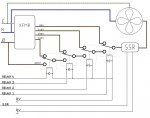
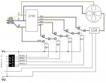
OK I made some drawings. I hope they are a bit decent optically and correct in their substance.
Photoshop drives me crazy. Keeps nagging about "need simplifying"...

The circuit posted by Dave was altered a bit, the ULN 2803 sinks current so V+ and V0 connections to the change-over relays had to be switched.
Also the ULN 2803 has back EMF diodes integrated, so I suppose the diodes at the 4 change-over relays could be omitted; I also suppose leaving them there won't hurt. Also I read somewhere that interferences should be stopped ASAP (where they occur) so they seem to be well placed.

As there was little room left I made a separate drawing for the PICAXE logic circuit. The power connections to the PICAXE are not shown, unused connections to the are omitted (no pins indicated anyway).
Concerning the connection to the solid state relay the solids have quite some circuit themselves : zero cross, optocupler etc.; limiting the input current with an additional resistor seems not to be necessary.


Concerning the relay 7pcv2415 (proportional controller); it seems to be hard to get in Europe, but digi key can deliver them in six weeks (no guarantee of course), they cost around 60euro. Not sure about delivery charges though.
The 12pcv series was available by another supplier although not in small quantities. 12 means you need up to 12 volts to control output voltage (as opposed to up to 7 volts with the 7pcv series).
Somehow I haven't found other SSRs of that type, though they offer a great functionality. So I am pretty sure there is lots around. Proportional controller seems not to be the relevant "catchphrase" concerning this type of equipment.


[Edit]: start
Added lables for change-over relays to picture
[Edit]: end

Regards,
Florian
 

Attachments

Last edited:

BCJKiwi

Senior Member
The simplest way to speed control typical ventilation fan motors is to use capacitors - just switch more or less capacitance into the AC. Use the specifically designed run Capacitors.

Suggest you call and discuss with a commercial Fan supplier that works in this area - they will be able to assist.

Have done this on more than one extract fan.
 
Top