robert.higginson
New Member
Please bear with my request as I am new to this and so not at all good.
I have successfully used and program the various project boards and want to create similar (but simpler) on a breadboard to control a simple 3v toy motor, a LED, and a LDR using a 18pin PicAxe (18M2). I know that this might be overkill but it is the chip (18pin) that is used in the buggies and T4 project boards so I would like to keep things the same. The breadboards will all be powered by a 3x1.5v battery pack.
I have no background in electronics (only 20+years programming) but will have to teach a unit concerned with micro controllers and so am trying to teach myself and create some step by step material before next term and make it interesting and practical. I believe that I should use a L293D to control the motor (?) forward/reverse action.
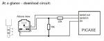
Is there any way that anyone could give") confused me any help of laying out a breadboard for this circuit including the programming circuit, or suggest somewhere I could seek help. I have ‘Googled’ my way through the internet and looked at these forums but cannot find anything that I understand and can use as I cannot find an ‘Idiots Guide’ or reply. I think one of my problems started with the diagrams I am following (section1/page 33 of the manual) but it does not seem to use the 3.5 jack and so I am stuck where the 1-2-3 pins are located.
confused me any help of laying out a breadboard for this circuit including the programming circuit, or suggest somewhere I could seek help. I have ‘Googled’ my way through the internet and looked at these forums but cannot find anything that I understand and can use as I cannot find an ‘Idiots Guide’ or reply. I think one of my problems started with the diagrams I am following (section1/page 33 of the manual) but it does not seem to use the 3.5 jack and so I am stuck where the 1-2-3 pins are located.
Hopefully there is someone reading this who will take pity and help me out and explain things in a simple way suitable for an 'idiot' - I would be thankful for any help.
I have successfully used and program the various project boards and want to create similar (but simpler) on a breadboard to control a simple 3v toy motor, a LED, and a LDR using a 18pin PicAxe (18M2). I know that this might be overkill but it is the chip (18pin) that is used in the buggies and T4 project boards so I would like to keep things the same. The breadboards will all be powered by a 3x1.5v battery pack.
I have no background in electronics (only 20+years programming) but will have to teach a unit concerned with micro controllers and so am trying to teach myself and create some step by step material before next term and make it interesting and practical. I believe that I should use a L293D to control the motor (?) forward/reverse action.
Is there any way that anyone could give
confused me any help of laying out a breadboard for this circuit including the programming circuit, or suggest somewhere I could seek help. I have ‘Googled’ my way through the internet and looked at these forums but cannot find anything that I understand and can use as I cannot find an ‘Idiots Guide’ or reply. I think one of my problems started with the diagrams I am following (section1/page 33 of the manual) but it does not seem to use the 3.5 jack and so I am stuck where the 1-2-3 pins are located.Hopefully there is someone reading this who will take pity and help me out and explain things in a simple way suitable for an 'idiot' - I would be thankful for any help.