A confused teacher.

AllyCat

Senior Member
Hi,

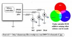
The Serial In resistor (R5) is incorrectly wired to ground instead of to the input pin. The PICaxe's internal "Weak PullUp" resistors can save a few external components (e.g. for the push-switch), but perhaps the "Active Low" concept (also giving lower output voltage drops for the LEDs) may be more difficult for young students to program?

What is the external supply voltage? The diode will drop at least 0.6 volt, the PICaxe outputs more than one volt (there was a recent thread about this voltage drop) and a blue LED is likely to require 3 volts, making the series resistor rather small.

Also, it's generally recommended NOT to make LEDs share a series resistor because their currents may not balance.

Cheers, Alan.
 

Goeytex

Senior Member
The Forward voltages of a typical RGB LED are as follows:

Forward Voltage (Red)
Min 1.7
Max 2.1
IF = 20mA @ 2.1


Forward Voltage (Green & Blue)

Min 3.0
Max 3.3
IF 20ma @ 3.3

This means that the resistor(s) must be smaller for the Green & Blue LEDs compared to the RED Led.

Some LEDs may not be "typical" and there can be variances from one LED to the next. LEDs in parallel as in the drawing may not turn on at the exactly the same time, and may have a variance in brightness given the same forward voltage. However, many devices incuding HP light engines use LEDs in a parallel, or series/parallel arangements.

IMO the circuit should be breadboarded and tested for the optimal resistor values.

My strong preference would be to use Common Anode RGB LEDS and to drive each pair with a low side NPN transistor which eliminates the voltage droop from the Picaxe I/O pins. Using a transistor allows full voltage to the LEDs, thus allowing full brightness (20 ma) if desired. It will greatly improve the color effect for the project, giving predictable results in regarding forward current vs voltage. Using transistors also reduces the current through the Picacxe to a bare minimum. I think of the Picaxe (and micocontrollers in general), as logic devices not LED drivers.

The penalty for using the transistors (3) is about 50 cents worth of components and bit of board space. But the final product is more robust, more efficient and will give a much better effect since the LEDs will have full range. (0 to 20ma)

Goey
 

Morganl

Senior Member
You will receive many correct answers.

For much power to the led use FETs instead of bipolar+resistors, saves space, build time, complexity and even cost nowadays. If SMT is OK there also exist NPN or PNP with resistors built in.

But why more than one LED? I would choose one small and efficient (for good visibility in strong ambient light) that can be supplied by only serial resistors.

You can have the LED + serial out always connected (no need for jumper) especially if that is the blue LED.

For supply i would consider using USB battery packs: they supply regulated 5V plus have become cheaper than the bunch of cells the school would have used in a couple years.
Decide some common supply connector for your devices 5V supply. I have settled for the 1,3/3,5 mm barrel, such as http://www.ebay.com/itm/301179743610
One of my USB pack came with a bunch of conectors and that was one of them (used for i.e some nokia phone). Also there exist wall power plugs with such connector supplying 5V.
 

manuka

Senior Member
So now it is time for the next project
Reynoldsw87: Oh dear- does this mean the original project is now signed & sealed ? What about the diverse educational, constrained time (13-14 hours total delivery !) & practical issues earlier mentioned !? Are these projects just classroom modules or intended as take home? Kids at this age still absolutely LOVE "look mum what I made" creations, & they could get you valuable parental Brownie points too.

Best you also clarify that your "Y8* pre teen students are/aren't technically "green". In my extensive UK/NZ experiences most at this age,although usually admirably teachable, these days will NOT know a resistor from a reef knot or a microcontroller from a mousetrap...

But at the 2nd quest- modern LEDs can be near blinding on even 5mA. I've some reds here that are absolutely EVIL at that current. How about hence simply optically combining individual Red, Green & Blue LEDs on 3 PICAXE PWM driven outputs to produce assorted hues? This would additionally help students appreciate RGB additive colour mixing, as well as the superior green sensitivity of human eyes. (Refer a web demo here - scroll down.)

EXTRA: Just spotted! Best avoid 4 x AA cells too, as fresh alkalines can initially deliver ~1.7V each, meaning any controlling PICAXE would be threatened with a >6V oversupply. 3 x AAs have long been considered a PICAXE supply standard, especially if used in a switched battery box. Many folks now use only 2 cells, but of course this will put you up against the ~3V supply needs of blue LEDs,

Stan -old chalkie & parent of 4.
 

Attachments

Last edited:

reynoldsw87

New Member
Manuka Other project is far from being signed off and complete. I have got it on to a bread board and now in the stages of the PCB being developed to fit the vibrating bug. Next stage is to test it on a range of students over lunch times. The project may be kept as an after school club, really don't know at the moment. We currently do an MP3 speaker in Y8 and students have plenty of time to produce a circuit board and do the theory at the same time.

What PICax would I have to use to have to have 3 PWM outputs? I thought an 08M2 only had one?

Morganl Thank you for the idea of the USB battery pack. Someone has mentioned before about using a USB lead plugged in to a computer as a power source. Not entirely sure about that though .

I will drop the design to have only 1 LED. I am hopefully going to get it on the breadboard later this weekend.
 

premelec

Senior Member
14M2 PICAXE has 4 PWMOUTs available at slightly higher price and 20M2 same with more pins and almost same price as 14M2 last I checked...
 

manuka

Senior Member
Re PCB being developed to fit the vibrating bug - details & pix appreciated! What motor?

Re MP3 speaker -(assumed for tablet or mobile phone) - electronic amp or an acoustic resonator?

Re plenty of time for circuit board & theory - don't you only have 13-14 hours TOTAL ?
 

lbenson

Senior Member
Regarding the powering of picaxe project from usb, that works well. This 7-port powered hub would enable you to spread the power around:

http://www.ebay.ca/itm/7-Ports-USB-2-0-Hub-High-Speed-with-EU-Plug-AC-Power-Adapter-for-PC-Laptop-/131143767816?pt=US_USB_Cables_Hubs_Adapters&hash=item1e88c71708

You can break out the power with these serial dongles even if you don't need the serial part.

http://www.ebay.ca/itm/1pcs-USB-2-0-to-TTL-UART-6PIN-Module-Serial-Converter-CP2102-STC-PRGMR-Cable-NN-/161297924274?pt=LH_DefaultDomain_0&hash=item258e1b00b2

These cables can be stripped off 2 at a time and used as extenders:

http://www.ebay.ca/itm/40Pin-30cm-Dupont-Wire-Color-Connector-Cable-2-54mm-Female-1P-1P-For-Arduino-/390832612156?pt=LH_DefaultDomain_0&hash=item5aff70633c

One advantage of using separate battery boxes is that a short in a circuit won't damage other student's circuits. I don't know what kind of circuit protection these hubs have. In theory, shorting one should shut it down without turning off the others, but it might be different in practice. If you get one, I would check it to see if a short cuts off the other usb ports, and if the shorted one recovers after the short is removed.
 

reynoldsw87

New Member
manuka I have decided to make the actually vibrating bug bigger, so the original small vibrating was not powerful enough to move the toy. I am now going to use this: http://www.technologysupplies.co.uk/dc-motor-1-5-3-volts-model-10.html and then laser cut out an off centre cam to fit on the shaft. I know have to find a way to mount the entire project together with the battery box.

If I am honest I think the project will be a non starter due to other teacher not wanting to combine with me in a technology rotation. Hence moving on to the mood light and s robotics program (circuit diagram to follow soon).

Yep 13-14 hours in total. Students pick up soldering really quickly. In Y7 I do not let them move on to the actual project until they have solder 10 - 15 good joints in a row. Yes we end up getting through a lot of test boards but it means they are practising.

Y8 - Students use test boards to practise soldering. Then before we add a component to the board we do the theory behind it and then solder it to the board. We continue to do this until all 16 components are added. Yes you get the odd student through that the soldering is hideous but a most of the time the joints are to a very good standard. At time they hate me for the amount of practising I get them to do but I am determined to keep standards high from Y7.
 

AllyCat

Senior Member
Hi,

For simple projects, the 08M2 is "usefully" cheaper than any of the other PICaxe chips. But in terms of "bang per buck" the 14M2 (and above) offer far better value for PWM, RAM and Program sizes, etc., with the 20M2 easily offering the lowest cost per pin. But of course Rev.Ed.'s "educational pricing" may be different, so it's worth checking for quantity discounts, etc..

For the power supply, I can certainly see the "appeal" of AA cells, particularly in an educational environment. However, it should be appreciated that although primary cells (Alkaline and those horrible "carbon", or so-called "heavy duty" types) start at 1.5 - 1.6 volts per cell, their voltage falls almost constantly to the manufacturers' "end-of-life" figure of only 0.9 volts. So if you design your circuit to work only down to say 1.3 volts, then you will get less than half of the rated (or available) power from the cells.

Now that might not matter if you take fresh cells from a pack for each student and they "disappear" at the end of the lesson or course (either if the project is taken home, or otherwise). But if you need to get "value" from your cells then you should design to work at least down to 1.2 volts per cell. That then opens the door to using rechargeable (NiMH) cells which have the great advantage that they deliver a much more constant voltage over their discharge cycle (typically from only 1.3 volts down to 1.2 volts).

Some maufacturers are now offering "budget" versions of their NiMH cells with a lower capacity (either admitted as such, or hiding behind "fake"/noname labels). Of the "honest" offerings, 2 x 800mAh NiMH AA cells from a (well known) "Pound Store" (i.e. 50p each), may have much less capacity than is possible from the technology, but will probably still give as much output (per charge) as an Alkaline being used over a limited range, e.g. 1.5 down to 1.3 volts.

The more constant voltage from rechargeables makes the design for driving LEDs much easier. Bear in mind that your original design would have fairly fixed voltage drops of about 0.7v for the series diode and 3.0+ v for the blue/green LEDs, so the resultant change in current between 6 volts and even 4.8 volts is rather large (and proportionally different to that for the Red LED). Also, expanding on what has already been said (or implied), the PICaxe has a rather weak pullup current capabilty (rated 3.5mA @ 0.7v), pulldown is somewhat better (8mA @ 0.6v), but still far inferior to even a small external transistor (say 20mA @ 0.2v).

Cheers, Alan.
 

eclectic

Moderator
@Alan

What happens when (not if),
one of the little dears "accidentally" short-circuits

an Alkaline, then fully-charged NiMH?

e
 

manuka

Senior Member
- I think the project will be a non starter due to other teacher not wanting to combine with me in a technology rotation.
Sigh-welcome to professional jealousy. He's probably so comfortable with his "fuse tester" that your student focused, state of the art enthusiasm is considered an irritating threat. I encountered a lot of such unsupportive "if youth only knew, if age were only able" culture during my own early chalk face years...

But enough from me -IMNSHO it seems you will sink or swim without us old hands publicly posting.
Best send me a PM if you've further needs. Arrivederci - Stan.
 

reynoldsw87

New Member
Good evening all,

Firstly I would like to say thank you all for your help over the last few projects. I have made prototypes of both the RGB Night Light and Vibrobug. However with moving school at the end of the academic year, the school have decided to ditch the projects. This is part of the reason I am moving on.

I will post prototypes of the models I have made over the next couple of days. Bloody annoying that they have been ditched after all this time and effort has been spent on them but oh well.

I am moving on to a project for the new school now. I was wondering if people could check over the CD. The idea is to have a basic board that is attached to a robot chassis. The board can then have multiple I/O added to the board to turn it in to 3 robots: A line following (LDR and LEDS), A bump robot (microswitches) and a Ultrasonic robot (using SRF004).

I have been set a VERY limiting budget as the idea is to produce a low cost robot that can be used to help get students in to robotics from a young age. It has to be simple enough for primary to plug and play and then 15 y/o to be able to added extra I/O as they see fit.

Thank yo in advance. Will

View attachment Educobot - Project.pdf
 

manuka

Senior Member
Will: Phew-are you sure a fresh project is worth your energies? My modest experiences in classroom education indicate young teachers may be near overwhelmed with the culture & kids at a new school. Best go with the flow for QUITE a while ...

Once settled you should specify that you're employed to teach,not design and build classroom learning aids. It's akin to a pilot being expected to also organise his planes construction! Some countries (sadly - not my own...) have teacher expectations that every last nut,bolt & handout are organised for the educator to go with. I don't think this way myself,although I did experience it under the 1960s-70s PSSC Physics program.

But why re-invent the wheel? Line following robots already abound,including of course Rev. Ed's own. For youngsters (when classroom organisation & ruggedness are also important) you can't beat the "Snap" plug & play approach. A versatile pathfinder kit sells here in NZ (as "Brain Box") for about UK20-25 pounds. All manner of PICAXEd enhancements (including my own) have arisen to such approaches - see this perhaps.

Mmm- just what is your "VERY limiting budget"? For forum members in industry ("Dippy" ?) it'd be orders of magnitude more than you probably have to wrestle with... Stan.
 

AllyCat

Senior Member
Hi,

Educational pricing and requirements may be different than for us "home builders", but here is my 50p-worth (perhaps literally).

I'd base the design on a 20M2 (one of only a few good reasons for "rolling your own"); marginally cheaper than the slightly dated 18M2, and compatible with the usefully lower-cost 14M2 and 08M2 which fit in the same socket (with obviously less available I/O pins).

Most of the external pull-down resistors could be replaced by the chip's internal weak pullups (with minor software changes).

Generally, low-side switching of loads (e.g. LEDs), either directly from a PICaxe pin or via an NPN transistor, can drive larger currents (e.g. brighter LEDs and/or lower supply rail voltage).

Phototransistors may be more suitable for line-following than LDRs; perhaps cheaper and have built-in "lensing". But of course they must be connected with the correct polarity.

The diodes across the motors will only permit the motors to rotate in one direction, which makes the H-bridge chip a very expensive driver (and perhaps with self-destructive capabilities) ! Arguably, separate (discrete) transistors (even to make two H-bridges) could be cheaper than a '293 chip.

I believe we've already discussed possible battery supply arrangements for the previous projects at length, but don't see any detail in this diagram.

Cheers, Alan.
 

reynoldsw87

New Member
Alan,

Silly mistake my end, I still had a cheap dc toy motor in my head when adding the diodes. They have now been removed so that the driver will turn the motors both way.

Power supply will be 4 x AA batteries, I know that some say that I only need 3 x AA but the motors run well at 5V and SRF004 also needs 5Vs

I am making the board because I can not justify spending £17 for the complete kit or £4 for the PCB (http://www.rapidonline.com/Design-Technology/PICAXE-Controlled-Model-Kit-63809?SST=2).

I will be using these motors (http://www.rapidonline.com/electrical-power/1-120-inline-motor-and-gearbox-37-1217) and they run comfortable at 3-6V.

I will look in to photo diodes, see what sort of price I can get for them. Are they far better than an LDR?
 

AllyCat

Senior Member
Hi,

I will look in to photo diodes, see what sort of price I can get for them. Are they far better than an LDR?
Not necessarily "far better", but certainly "different". It's dangerous to generalise, but the principle differences are that most photransistors have a built-in lens (as do LEDs) so can have a fairly directional response, whilst LDRs are generally a "flat plate collector". LDRs respond primarily to visble light whilst (unmodified) silicon photodevices respond to both Visible and Infra-Red light. LDRs are arguably "slower", but probably not significantly so in a motorised robot application.

Personally I use the phototransistor from Rev Ed, but it's easily overlooked because it's described as an IR device in the LED section here ! It does have a "peak" response in the IR region, but as it's a silicon device in a "water clear" package, it also responds well to visible light, over most of the spectrum. However, I haven't had much success finding a full data sheet for the "ST-7L".

As for the power supply, personally, I'd connect the motor driver directly to the batteries (with a fuse if appropriate) and connect (only) the PICaxe supply via a diode, or even a (red) LED to also indicate when power is "on".

Cheers, Alan.
 

premelec

Senior Member
With regard to cheap - note that LEDs in general generate a voltage when illuminated - pretty low current/voltage but sometimes useable...I used some on a READADC on a 8M2 unit successfully. [I experimented with also lighting the same LED on the same pin as it detected light].
 
Top