433 MHz band monitoring receiver

manuka

Senior Member
Those data pins are already joined on the ZW3102. Just in case another offering is used perhaps indeed the PCB should not have them connected. Stan.
 

Attachments

Grogster

Senior Member
@ manuka - PM - OK.

@ SAborn - good points you make - can enlarge the ANT connection to whatever is desired. I agree that whips directly soldered could break a smaller pad from the board. Which pins are which with the analog-vs-digital you mention for the data pins on other modules you have seen? I can remove the bridging track on the two data pins easy-peezy, and would be a good thing if there is potential for something nasty to happen there, but I would need to know which data pin is the digital one on the modules you mention, so that the PCB is compatible with either module.

The physical module I was using here as a reference also has both data pins connected on the module.
My module is an RXD1, but I am pretty sure I got it from Jaycar.

EDIT: Just looked in my RF modules, and I also have an RXB1, exactly as in Stan's photo.
Both the RXD1 and RXB1 appear to have exactly the same pinout, both having the data pins connected on the module itself. Would still like the extra info though, as then that would correct the PCB, and the RXB1/RXD1 modules themselves would not care...

EDIT
 
Last edited:

manuka

Senior Member
As often noted before, a near bewildering array of these cheapie 433 MHz ASK modules abounds. Here in NZ the Keymark RXD1 is sold by Surplustronics (Auckland) for just NZ $5.50, while Jaycar sell the Keymark RXB1 for more like 3 times this,no doubt due to it's tighter superhet. based performance. Spirit-On second source these modules for Keymark - they only seemingly differ in a stylised S rather than K logo.

The main reason I'd probed the Jaycar offering for RSSI relates to wide Aus/NZ supply at the numerous Jaycar outlets. Given that the scouts "sniffer" needs just a simple non data analog. receiver,I'd be more than happy to base it around the cheaper RXD1 (or for that matter anything akin & widely available!), even though the RXD1 has inferior performance (& probably no RSSI) due to it's regenerative circuitry.

Extra- as mentioned a few posts back, SparkFun also stock a similar "Holy Stone" @ US$5.95
 

Attachments

Last edited:

SAborn

Senior Member
The ones i have at present are RXB1 and not sure on the others as all working in there boxes.

The data pin used (digital data) is the second pin in from the end, the 3rd pin in is the analog data pin.

It might pay if you can to have the ant pad nearer to the board edge if you are able too, because some whips etc have a bolt on mount and a nice juicy fat pad that one could drill to suit would be good.
All this might be un needed as its more than likely be a wire ant used, but i found wire ants not so good on hand held moible stuff and the fixed whips far better.
I got my whips for around a $1.00 each and thought almost as cheap as wire.

What is the spacing used between pads and ground plane, as i like at least 0.6mm because it saves the hassle of bridges in home development of boards.
Its not that i can not go finer but why risk the chances of a bridge occuring in a area that dont really matters two hoots i think.

Others might want to copy your art work and i work on more is best where able.
The days of ultra fine tracks and pads have gone for me and for most circuit designs work with more rather than less where able, i see little point in removing copper if there is no real need.
Its like unused pads i still put a short track to nowhere just to give it some area on the board so they dont peel off when unsoldering or with poor soldering skills.
Im sure you have designed as many boards as me and have your own system, its just some of the rules i work to as a course of practice.
 

Grogster

Senior Member
The data pin used (digital data) is the second pin in from the end, the 3rd pin in is the analog data pin.
OK.

What is the spacing used between pads and ground plane, as i like at least 0.6mm because it saves the hassle of bridges in home development of boards.
Its not that i can not go finer but why risk the chances of a bridge occuring in a area that dont really matters two hoots i think.
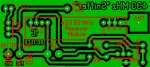
Original post was 0.4mm, but it is now 1mm to satify student requirements. ;)
It can be anything you like, but I have settled on 1mm based on the comments on this thread. As I say - can be anything you like.

Will upload a new version soon.
 

manuka

Senior Member
G: 1mm suits both novices & weary eyed seniors well I'd say. If you're tweaking anything more maybe say 433.92 MHz (rather than 433) as some outlets refer to it as 434 MHz. Given my musings above, before going too far it may well be worth testing (or making provision for) both the RXD1 & RXB1 in the sniffer circuit. Stan
 

Grogster

Senior Member
G: 1mm suits both novices & weary eyed seniors well I'd say. If you're tweaking anything more maybe say 433.92 MHz (rather than 433) as some outlets refer to it as 434 MHz. Given my musings above, before going too far it may well be worth testing (or making provision for) both the RXD1 & RXB1 in the sniffer circuit. Stan
Completely open to any suggestions.

I could add a jumper which would allow for either module, but my concern is that the jumper could be put in the wrong position for the module that is soldered in...

Opinions?
Thoughts?

Now, it's Friday night here, and i'm on the happy-sauce, so no more till tomorrowe. :)

EDIT: Well, maybe one more...
Attached is new image. 5mm ANT pad, addition of TACT swich in place of Squelch jumper.

Let me know your thoughts.
 

Attachments

Last edited:

SAborn

Senior Member
I feel im being picky of your work here and dont choose to be, so please see it as constructive.

The pad for the ant needs to be a square block running out to the edge, as the pad you have, if i fixed a standard bolt on whip to the board it would also short out on the ground plane.

It would be good if you could take the pad out to the other edge of the board as well, so it would allow for the ant to be mounted at either position 90 degrees to each other.

Another trick i do is to place a short track leading off the pads the full width of the pad to give a larger copper plate for the pad, then reduce my track to the chosen size and route off to where needed.

The way i see it is we shape the copper to suit our needs and is why i dont like many artwork packages because of the costraints within them.

As an example i will attach a board that has nothing to do with this project, but will let you see how i use the copper areas to give a bigger foot print.

The file name was for my own purpose and not surgesting you do this.

Its funny i spent years designing for fine tracks and pads and yes i can etch them, and then now find myself trying to leave as much copper in circuit as i can in projects that has no need to remove it.

Try doing the circuit with tracks as wide as the standard pads you used, it might look goofy to start with but will look good on the board. (like you done on the ant track)

Its the same amount of copper its just where you leave it is the way i see it.

I very much like your work and hope you see my comments as constructive rather than being negative to your design work.
 

Attachments

Grogster

Senior Member
No, I don't think you are being critical - thanks for the comments. :)

I can change the ANT pad to a square, no problems - Sprint Layout allows you to use round or square pads of any size - I just adopt the more standard round pads by defualt - personal choice more then anything else! :D

It would be helpful, if I knew how big the bolt is you are talking about - hard to make the ANT pad the right size, without knowing the size of bolt you MIGHT be wanting to use. Up to 1/4?(6mm)

EDIT: New pattern, 7mm square pad for ANT. Round pads, even if the bolt shorts out to the ground-plane, are easily overcome with the use of a nylon insulating washer on the PCB copper side. Have done it heaps of times. :) If I make the tracks themselves as big as the ant track, which is 2mm, the ground-plane will be broken in several places, so I prefer to leave the current track-width at 0.8mm - Unless you are using Dad's guttering soldering iron, you should not be able to overheat the tracks such that they unbond from the board itself. Not saying that can't happen, but even students in a classroom would be using the correct low-wattage soldering irons, one would hope. ;)
 

Attachments

Last edited:

manuka

Senior Member
Even nicer! Perhaps the PCB could be thinned across by a few mm from the current 30mm? This would better allow it to fit in the Klipo mini lunch box I mentioned earlier- see below. I'm increasingly thinking the whole thing can be just dropped into this nifty little box & the lid simply opened up when the unit is needed. The external antenna,which in it's simplest ¼ wave whip form is just ~175mm long, could be just curled up inside the box- see pix below. For close in work it wouldn't even be needed of course. The RSSI LED can perhaps be seen thru' the plastic of course- & maybe even the piezo can be heard?

Piezo elements in such a context work well either way round, so perhaps no need to label them red/black- save that for the battery leads! Please change that 4.5V to 5V ,or even ~5V,as well. Considering stray PCB ground regions, some of which depend at present on the 433 module pins for link up, maybe some of those isolated grounds could be joined too?

Mmm-that trial tactile switch is surely just a momentary contact one, which would annoyingly require holding down to activate squelch longer term. Although nice to mount on the board like this,a regular SPST toggle switch better suits. Such small slide switches are annoyingly elusive & costly of course- for unrelated projects I've taken to robbing them off solar garden lamps or torches/flashlights. Thanks to today's far superior LED offerings, even coin shops now can't give away such near obsolete filament torches.

My spies at Jaycar inform 1000s of their Keymark/SpiritOn RXB1 ZW3102 modules stocked around Australia/NZ (or held at their NSW Electus warehouse). I'm hence tempted to stay with these,in spite of numerous alternatives, as there's little chance of them being suddenly run out "down under"! In fact Jaycar may well lower the price (or consider a 433 MHz kit) to help move them before something better comes along. Stan.
 

Attachments

Last edited:

SAborn

Senior Member
Stan is that on of those New Chinese circuit boards you are using with the lunch box demo.
They tend to have a lot of dry joints i found.

Rather than the lunch box (i know Stan likes his lunch box) why not use a smaller version of the battery box you have there to mount the circuit into.
I often use the little battery boxes gutted out for mounting boxes, and it would give you your squelch switch built in.
Just glue or velcro the two boxes together and you would have a tidy little kit.
 

manuka

Senior Member
Yes- "paper thin" PCBs-they may be prone to dry joints but you can churn them out for peanuts!

I'm a great AA battery box fan myself,both "as is" & gutted, & had of course intended a 4 xAA type here for cheapness & long battery life. The switch on this was to do main supply on/off duties, meaning a 2nd switch will be needed for squelch. At one stage I even gutted a 4 x AA switched box & squeezed in a 4 x AAA (non switched) holder,fitting the 433 MHz circuitry in the narrow space freed up- see below. Things were just too tight- but this was before Grogster & his PCB design skills came along however!

I'm completly open still on design & have even again pondered mini breadboards (populated sample below), BUT the end result needs to be have a low BOM (~Aust$20),be cheap to run AND simple to assemble/fault find. As ongoing battery costs WILL be an issue I feel duty bound to organise things around cost effective batteries & had even considered a single rechargeable AA & ex solar garden lamp ZE002 "quadistor" approach. Stan.
 

Attachments

Last edited:

Dippy

Moderator
Go for breadboards Stan.

It just wouldn't be the same having photos of cheap/duff/Chinese made PCBs :rolleyes:

"they may be prone to dry joints but you can churn them out for peanuts"
- Is that very environmentally responsible? It's certainly the attitude that made China No.1 . Frightening.
 

manuka

Senior Member
You gentlemen DO realise those are NOT real PCBs, but merely scaled to size paper printouts?! Such a technique has long been handy to help visualise "what goes where" of course in the final job. Stan.
 

Dippy

Moderator
Fair play. I wasn't paying attention.... no excuses (like hangovers etc.)
I used to do the same cutout-to-try thing too.
Anyway, good luck with the RF scouts.
 

SAborn

Senior Member
I would have never guessed that was a paper cutout, it looked real. (Except the tracks were on the wrong side)

No Stan my eye sight is not that bad yet, and it was a tongue in cheek comment.

Bad on me.
 

Grogster

Senior Member
UPDATE: My main computer decided to die on me on Friday night, so typing this from the new one. Thank goodness I have full backups both as just file copies, and disk-images, so the basic new system is up and running again now, but I have yet to re-install the vast majority of applications, a couple of those being Sprint Layout etc. I will post an updated image, when I get time, but might not be for a day or so. :(

@ manuka - yeah, when I was looking at the squelch tact, I was kinda wondering the same thing, now that I have honed in on cost. I will put back the simple jumper for squelch - dirt cheap, but effective, and you can get hundreds of jumpers from old dead motherboards or hard-drives - I can even get some of my old computer which just so recently died on me!!! ;)
I will also look at shaving a few mm from the 30mm side as hinted.

@SAborn - Can you indicate a maximum bolt size please for ANT, so that once I get my software up and running again, I can make that change too.
 

SAborn

Senior Member
Bolt size is 2.6mm dia, the ant base is a 6.5mm piece of brass rod machined with a flat face on both sides and the hole is aprox. 3.5mm in from the end and 3.5mm back from where the machined flat starts.

The hole is not exactly centre across the flat face so allow a 8mm wide pad with the hole in the centre and it wont matter which way the ant is bolted on then.

So to recap... place the hole 3.5mm in from the edge of the board, 2.5mm inn dia, on a 8mm wide pad, 8mm deep.

Rubber/plastic section of the ant is 66mm long with an overall length of 78mm including the brass mounting section.
Rubber base dia, is 10.5mm and tip dia. is 7mm.

I was at the supplier to day and asked for Stan about availability, and they have around 600 instock and will do them for $1.00 each (or perhaps less) should Stan be interested.

I will post a photo when i get a chance to take one in day light.

They are what i would call a rigid whip and not over flexiable, but work well for a compact little ant.
Beats the hell out of a dangeling wire i think, and might cost less than the rca plug and socket in present design.
 

manuka

Senior Member
Good point- I'd be keen to see pix of them. Direction Finding (DF) initially may be just organised by simple body shielding & use of the RSSI LED, but we're considering scouts will rustle up simple Yagis eventually. Hence some sort of removal socket may be worthwhile. VERY close in(say < 10m) may cause RX swamping, & it's always handy to toitally remove any antenna & even shield the RX in a metal biscuit tin etc.
 

Grogster

Senior Member
Yeah, I'd like to see the photo too. :)

I have reinstalled Sprint Layout, so SHOULD be able to post an updated PCB image today or tomorrow, but I am not just resetting my computer - there are the normal daze chores to perform... ;)
 

SAborn

Senior Member
Hi Guys,

I took some photos of the little Ants, but it was late and the light level was fading, It should give an idea of what they are like.

I make a pin mount from a piece out of a terminal block and solder on, for my mounts but its fiddly and would not recommend it for the kids.

I will do 2 posts as we can only post 2 photos at a time.

Hope it helps you understand what i have been refering to.

Pete.
 

Attachments

manuka

Senior Member
SAborn: Many thanks for this & I certainly now get the picture. This whip antenna is probably a spiral inside that rubber covering. As it's intended that the RX can have a removable/interchangeable antenna (suiting DIY simple Yagi etc), all up I'm of the opinion a simple solid piece of wire attached to a RCA phono plug may be better. If it's too long initially,trimming to a resonant length can easily be checked as well. Sure- it may get lost, BUT at a pinch even a croc. clip lead may do. We're talking reception after all, so TX mismatch issues are not a concern.

The ability to direction find (DF) is quite an important aspect, both for the scouts & later users trying to track down annoying nearby interference too. When very close in you'll need to remove the antenna totally & sense direction by "body shielding".

I've just looked at another project case option- ref pix below. This uses a different Sistema 200 mL box, which is sturdier (& has 2 durable clasps) but slightly cheaper. Batteries would have to be in a different pak (perhaps Jaycar's PH-9200 4xAA squared as shown-not switched), but the area available for the PCB would then be MUCH greater. Thoughts?
 

Attachments

Last edited:

moxhamj

New Member
Ah, I see SABorn. And the RF module fits into the two sil sockets?

I guess you add a tiny amount of wire length with the PCB trace to the antenna. Hopefully it does not take it too far off the tuned peak.

I totally agree with these antennas vs 'a bit of wire'. From a practical perspective, 'a bit of wire' = soon to be 'a bit of shorter wire' *grin*. And looking at pre-made boards there will always be a bit of a gap between the chip and the antenna and I think your design looks about the same as an Appcon one so you ought to be ballpark right there.

Re manuka "This whip antenna is probably a spiral inside that rubber covering. " yes, I pulled one apart once and it had a coil then a straight piece of wire. Different designs will be different, eg the new Appcon ones are shorter than the Hope ones, so maybe the loading coil has a different inductance?

Hmm, are the scouts allowed to drill a hole in the lunchbox for the antenna? And, dare I say it, are they allowed to drill said hole with, shock, a soldering iron??!
 
Last edited:

manuka

Senior Member
DR_A: Cheap but sturdy cordless drills are thick on the ground almost anywhere now- I've even spotted pre schoolers using them ( c/w a wide diam. bit!) at a nearby kindergarten. Drilling holes in the plastic case hence is likely to be of little concern. Stan
 

SAborn

Senior Member
Hi Dr_Acula,

Should you find the ants of interest Aztronics in the city has them.
I find they work well for a quick neat little ant of 433mhz. and cheap.
 

Grogster

Senior Member
Yes, interesting.

@ Saborn - Yes, interesting - thanks for the photos - really helps me(and others I expect!) "See" what you are talking about. :) I was actually thinking of something you bolted onto the PCB - see attached photo. In your case, would it not suit you better to use your soldered-on-wire method, and just mount through a smaller PCB pad? I guess this opens things up to snapping off etc. Personally, I still prefer the bolt-on ones. You can get these from RFMA in Australia - that's where I got the one in the photo. I will try to get an updated image up by tonight.

@ manuka - I too like these little Sistema boxes with the clip-on lids. Depends on cost at the end of the day. The dinky wee lunch-boxes are dirt cheap, what is the cost of the Sistema boxes? It may not be much more - I guess it comes down to that $20 budget again... ;)

EDIT1: Forums won't let me upload the photo - I get the upload window, but it just stays blank forever, and I never get the normal upload options of that window. Will try again later...

EDIT2: There we go - temporary problem with the uploading, obviously.

These would not suit the "Sniffer" project due to width of 15mm at the base, and cost of about AUS$10 each, but I post the image, so you can see what I was thinking you were thinking of. :D
 

Attachments

Last edited:

Grogster

Senior Member
New PCB pattern.

- New size 68mm x 30mm - shaved 2mm from ANT end of board.
- Squelch tact replaced with jumper - you can either use a jumper, or wire to external switch if you want.
- ANT pad is now 8mm x 8mm - should be pretty right now with any luck, SAborn! ;) :D
- 433.92 added to decription of module - no room on PCB, unless I make the PCB text smaller?
- Piezo red/black wire references removed
- +4.5v changed to +5v, along with a RED marker for the battery wire

Anything else we can do?
 

Attachments

manuka

Senior Member
Grogster: Nice one ! Since we've got you firing on all cylinders, how about waving your magic wand over that other 4 xAA square battery holder option? It's just NZ$1.90 at Jaycar (versus NZ$3.90 for their switched 4xAA flat version). Although a switch would then need fitting, & wiring run to it, the real benefit of course is that PCB space then could be greater- perhaps as much as ~60mmx 60mm ?

Although momentary switches abound, the need to source & mount a boring SPST supply switch (perhaps two if squelch is external) may be a costly hassle. Anything protruding may be accidently knocked on as well. Such simple items can make or break a project, both at the BOM & user interface level! In the past I've even pondered mains rated ye olde bedside lamp types (Jaycar SP-0736) for simple projects, as they're cheap,NOT accidentally switched, easily single hole mounted & have screw terminals. Hey some of them even glow in the dark, but they'd look pretty clunky on something like this 433 MHz sniffer!

OK on the other "Sistema Klip IT" lunch box layout. Aside from the sturdy "wing" clasps,prices may make it slightly more appealing, as a pack of 3 is just NZ$5 at the red shed (~NZ$1.60 each).
 

Grogster

Senior Member
Any reason why we couldn't just have another jumper as a power switch?
I've done this before in the past(for low current stuff!), and it works a treat - and VERY cheap.

I can resize/redraw for 60x60, but that will take another couple of days.
 

manuka

Senior Member
Update: In spite of Grogster's nifty PCBs (which still may be used!),in the interests of both economy & assembly ease we've initially run with the boxed bread board version below. The circuitry (& -ah-it's initial exploratory hacks & bugs!) has been refined into a "2 stager". Performance has been quite remarkable! Assembly details, antenna & PICAXE transmitters etc will eventually be hosted at a support web site => www.picaxe.orconhosting.net.nz/433rx.htm Stan.
 

Attachments

Last edited:

SAborn

Senior Member
Very good Stan, but it worrys me with todays age becomming a plug and play way of life and no real skills learnt except to copy things parrot fashion.

If you are worried about their ability to be able to solder a simple circuit board than what hope in hell do they have at soldering the wire to that tiny little hole/pad on the receiver....even i would struggle without 2 morning coffees first.
 

westaust55

Moderator
I will do 2 posts as we can only post 2 photos at a time.

As a suggestion, what I often do is to create a "Collage" where I put two or three photos/images into the one jpeg file. As long as the total does not exceed the forum file size limits helps keep like information in the minimum number of posts.
 
Last edited:

manuka

Senior Member
SAborn: Fair comment - but let's face things & recognise that much hand soldering is now at the mend broken wires/attach connector/replace faulty component stage anyway! Learners still have to solder header pins etc on this project, & a soldered version can be made on a matching layout Kiwi Board if need be of course. Aside from the pretty rigid Aust$20 a head BOM, a realistic aspect of this scouts project has been that JOTA facilities may well be outdoors,although under canvas on trestle tables. We're also considering extending the whole thing (perhaps as a soldered PCB kit ) with PICAXEd READADC - this may easily end up more like twice the price however...

Re that RSSI tap- it's a generously gold coated PTH (plated thru' hole), & once the thin wire is pushed through just simply twisting it tightly has been enough for reliable contact in every case- so far! Only tiny currents are being delivered after all. Soldering is certainly best, but my much knocked around prototype has not yet missed a beat. Stan.
 

manuka

Senior Member
Yikes-4 years gone in a flash...

This "433 MHz Sniffer" project was eventually published in the Jan 2011 "Silicon Chip" electronics monthly. However Dorji's superior & cheaper 433 MHz ASK modules became available not long afterwards, & I went on to explore their use in a popular DF Instructable - see details from P.12 onwards.

The classic Jaycar module design apparently still has project appeal, but it's recently been drawn to my attention that their ZW-3102 receiver now has been upgraded with a different (& perhaps superior ?) PT-4302 RF IC. See below- & be aware that "B" means BIG -the new module seems unacceptably large for today's circuitry !

This new release has shown some promise for RSSI tapping, as 0.9 - 1.4V is present at the RF engine pin 14/C5 junction. Sound output is better than before for "sniffer" work, & the stated (yet to be properly confirmed) increased sensitivity & suprisingly wide supply voltage needs (pleasingly verified) may give it appeal in diverse projects. Stan.
 

Attachments

Last edited:

manuka

Senior Member
Just sent in response to an "Ask Silicon Chip" query.
Jaycar's new ZW-3102 433 MHz data receiver (based around Princeton Tech's PT4302 RF IC ), is thankfully pin for pin compatible to their traditional ASK module. Aside from their intended data duties, band "sniffing " persuasion gives piezo based audio that also seems superior in both in volume and clarity to their classic Keymark offering.

The module especially scores over Dorji's cheaper 433 MHz receiver for it's ability to work down to 2.4V. Such a flexible supply nicely suits powering by a single Li coin cell, single LiFePO4 or 2 x AA etc.

It's shown itself significantly more sensitive than before. Semi line of sight signals (through light vegetation and wooden buildings) from a 25mW tone sending Dorji transmitter were still audible when some 100m away.

Data sheet sleuthing pleasingly reveals a signal strength point at PT4302 pin 14 ,which conveniently runs to a good solder point at SMD capacitor C5. A wire can be run from this to a duplicated module data pin that's freshly isolated (by PCB track cutting).

The voltage swing here suits useful RSSI work, as it varies between 0.9V with just band noise and ~1.4V with a strong nearby signal. DMM monitoring here could allow keen insights into transmitter,propagation path and antenna performance. A simple LED (perhaps wired via a boosting Darlington Pair) however could be enough for proximity and visual checking on such suspect transmitters as 433 MHz wireless doorbells.

As these ZW3102 modules are available off the shelf at any Jaycar they may be worthwhile for general 433 MHz use, even though they're more costly than other offerings.
 

Attachments

Last edited:
Top