3 pin ceramic resonator
- Thread starter 69-cat
- Start date
lbenson
Senior Member
Which chip are you using? Current 28X2s and 40X2s +can+ use an external resonator, but don't need one unless you are using the highest clock speed possible, or perhaps have some baud rate issues.Sorry but first time using a chip that required the external resonator....looking to use the 3 pin unit so just asking is there a device that you would use?
hippy
Ex-Staff (retired)
Any of our resonators can be used, and pretty much any which look like them -
https://www.picaxestore.com/electronic-components/resonators-and-crystals
For a PICAXE 28X1/40X1 or 28X2/40X2 chip you are probably after a RES036 8MHz which gives 32MHz operation or RES037 16MHz which gives 64MHz operation.
https://www.picaxestore.com/electronic-components/resonators-and-crystals
For a PICAXE 28X1/40X1 or 28X2/40X2 chip you are probably after a RES036 8MHz which gives 32MHz operation or RES037 16MHz which gives 64MHz operation.
inglewoodpete
Senior Member
I just buy unbranded 16MHz 3-pin resonators from any electronics store that stocks them (and that includes the PICAXE supplier in my country). I have not had any problem with them.
As hippy implies, the PICAXE configuration activates the base PIC's x4 phase-locked-loop when an external resonator of crystal is selected.
As hippy implies, the PICAXE configuration activates the base PIC's x4 phase-locked-loop when an external resonator of crystal is selected.
westaust55
Moderator
What is the intended project/application requiring the resonator?
From a model railway related website many members there have been having problems with resonators (4, 8 and 16 MHz) from various sources in conjunction with PIC related projects. Seems that the resonators do work but are often out of tolerance. In particular their CAN communications bus related modules using 16 MHz resonator seems the modules do not function properly or at all. On that website, some of their modules designers/builders have switched to crystals plus capicitors and the problems were solved. In other cases swapping out the resonators also solved the performance issues.
Seems a bit of a lick of the draw on resonator quality.
unfortunately no information found on the sources they have used to buy the resonators but there have been references to multiple colors (blue and beige) and I doubt all are buying from the same source.
The project is nothing fancy but will be using serial 9600 baud to communicate with an MP4 Sprite video player and 3 MP3 DFPlayers for a Halloween prop controller. Project will have 3 witches talking to and sometimes over each other along with video projection into a crystal ball, well it looks good on paper!
Dave
Dave
Hemi345
Senior Member
Got any links to these issues? Curious if they mentioned impedance or load capacitance values for the resonators that worked well. I bought some CSTNE16M0V53Z000R0 (surface mount) from Mouser for a 28X2 project but haven't tried using them yet. Hopefully they'll work fine since they're from a well known manufacturer and the fact I already sent off to have the PCB made based on that resonator's footprint.What is the intended project/application requiring the resonator?
From a model railway related website many members there have been having problems with resonators (4, 8 and 16 MHz) from various sources in conjunction with PIC related projects. Seems that the resonators do work but are often out of tolerance. In particular their CAN communications bus related modules using 16 MHz resonator seems the modules do not function properly or at all. On that website, some of their modules designers/builders have switched to crystals plus capicitors and the problems were solved. In other cases swapping out the resonators also solved the performance issues.
Seems a bit of a lick of the draw on resonator quality.
unfortunately no information found on the sources they have used to buy the resonators but there have been references to multiple colors (blue and beige) and I doubt all are buying from the same source.

westaust55
Moderator
The information I have seen is on the UK based MERG closed forum and there also references Microchip forums (but no links).
From my re-reading it appears for the MERG group that 18F K series PIC chips as used for the PICAXE X2 range are involved.
It is not the PIC itself but the resonator requirements.
For example, for a 16 MHz resonator the ideal resonator has 22 pF Capacitance but these are apparently hard to come by and so some folks are using 30 pF resonators that are proving to be borderline.
Other cases again the capacitance for the resonator may be too low and folks find the circuit is not working at the correct frequency (referred to in a MERG thread as “lazy resonator” then when the builder puts a finger near the relevant location on/near the PCB the circuit starts to operate correctly -at the correct frequency so that the CAN Bus comms works.
One post suggest that 18 pF were even less reliable than 30 pF resonators. The poster for that statement later indicated they were Murata brand. There was mention that this information seemed counter to discussions on the Microchip forums (apparently involving MC engineers).
Hemi345
Senior Member
Well that's kind of discouraging. Hopefully it'll work out for talking to four I2C devices, a MAX7219, and some 9600 baud serial. I'll probably solder the PICAXE and resonator first and test as much as I can before adding the rest of the SMD components just in case it it's flaky.
WhiteSpace
Well-known member
Interesting - I seem to be having similar issues. I bought these 16MHz and 4MHz resonators the other day to try to speed up a 28X2 so as to get my OLED display to load more quickly. https://www.rapidonline.com/ael-ztt-mg-4mhz-4mhz-3-pin-piezo-ceramic-resonator-90-3565 and https://www.rapidonline.com/ael-ztt-mx-16mhz-16mhz-3-pin-piezo-ceramic-resonator-90-3573. Their capacitance is shown on the datasheet as 30pF, which I see above is a bit borderline. I should say that I bought them off a third party site only because I also needed some other bits and pieces that the Picaxe store doesn't do. I've just run a test that confirms my impression. I set the instruction Setfreq m16 at the start of the program then a loop of 5 LED flashes with pause 2000 for high and pause 2000 for low each time. It took just about 10 seconds, which suggests, if I understand correctly, that it's running at the standard 8MHz for a 28X2 - so taking half the 20 seconds (5 x (2000 + 2000)) based on the 4MHz reference speed for "pause". I connected the middle pin of the resonator to ground and the side pins to pins 9 and 10 of the Picaxe. Am I missing something obvious? Thanks. Presumably the answer is "should've gone to the Picaxe Store"?
techElder
Well-known member
WhiteSpace
Well-known member
Thanks very much. Presumably just connects to pins 9 and 10 with no ground connection?
techElder
Well-known member
Presumably just connects to pins 9 and 10 with no ground connection?
The OUTPUT of the oscillator connects to ? { I can't remember which pin to use for the external oscillator input.}
28X2, 40X2 internal k31, k250, k500, m1, m2, m4, m8, m16 external em16, em32, em40, em64
hippy
Ex-Staff (retired)
Whilst it does seem that there is some issue with crystal or resonator selection when using CAN bus this does seem to be an issue specific to CAN bus and similar high-speed asynchronous self-timed protocols.Well that's kind of discouraging. Hopefully it'll work out for talking to four I2C devices, a MAX7219, and some 9600 baud serial.
For low-speed serial there is a much greater tolerance to timing, in the order of +/-6%, and there should be little need for crystal or resonator control. Even less so for I2C and SPI where the bus runs at whatever speed the master presents.
hippy
Ex-Staff (retired)
I'm not sure what impression that confirms, what issue you are trying to identify or prove, or what it is you think you are missing.I've just run a test that confirms my impression. I set the instruction Setfreq m16 at the start of the program then a loop of 5 LED flashes with pause 2000 for high and pause 2000 for low each time. It took just about 10 seconds, which suggests, if I understand correctly, that it's running at the standard 8MHz for a 28X2 - so taking half the 20 seconds (5 x (2000 + 2000)) based on the 4MHz reference speed for "pause". I connected the middle pin of the resonator to ground and the side pins to pins 9 and 10 of the Picaxe. Am I missing something obvious? Thanks.
Five loops of High, Pause 1000, Low 1000, Pause 1000 on a 28X2 at its default 8MHz operating frequency will take 10 seconds to execute - Tested and confirmed.
Double the frequency to SETFREQ M16 and double to using Pause 2000 and it will take the same 10 seconds to execute - Tested and confirmed.
Note that SETFREQ M16 won't even select the external resonator.
Regardless of what SERTFEQ EMxx setting is used, the speed will be 4 x the resonator frequency. The 'xx' is purely informative.
With an 8MHz resonator fitted, SETFREQ EM32, frequency again doubles to 32MHz, so double to Pause 4000, and the five flashes takes the same 10 seconds - Again tested and confirmed.
hippy
Ex-Staff (retired)
If fitting a 3-pin resonator you need to connect the middle pin to 0V.Presumably just connects to pins 9 and 10 with no ground connection?
If fitting a 2-pin resonator or crystal you need to add two external capacitors, one between each pin and 0V.
The 3-pin resonators have the capacitors fitted internally.
hippy
Ex-Staff (retired)
I would describe it as a mix of each. CAN bus generally has a very tight tolerance, 0.5%, and, while the PICmicro oscillator circuitry can meet that using appropriate crystals and external capacitors, that's not so easy to achieve with resonators due to the oscillator design and the characteristics of most off-the-shelf resonators. In addition, the PICmicro does not have an internal oscillator which itself has enough accuracy to avoid use of a crystal or resonator.It is not the PIC itself but the resonator requirements.
The 'in practice' issue is that the on-chip oscillator isn't good enough, crystals and external caps aren't desirable, so people want to use cheap resonators, but they don't work well, and those which do are as expensive as crystals.
So on one hands it's; "there is no problem" - use a crystal with caps or an expensive resonator which does work. On the other there's the desire to use the internal oscillator or cheap resonators. Trying to do either is where the problems arise.
There are similar issues when it comes to PICmicro's driving high-speed USB and ethernet, but none of those issues should affect the PICAXE as it provides little in the way of interfacing which is reliant on a highly accurate oscillator frequency.
techElder
Well-known member
Sorry, Hippy, when using an external oscillator, I can't remember whether to connect to 9, 10 or both on the 28 or 40 X2's.If fitting a 3-pin resonator you need to connect the middle pin to 0V.
If fitting a 2-pin resonator or crystal you need to add two external capacitors, one between each pin and 0V.
The 3-pin resonators have the capacitors fitted internally.
WhiteSpace
Well-known member
Apologies - that was a very unclear post, not helped by leaving out a vital letter and compounded by a misunderstanding on my part. The impression that I thought that I was confirming was that the external 4MHz resonator wasn't making any difference to the frequency. I see that I wrote SetFreq m16 in my post above when what I meant, and what I had included in my program, was SetFreq em16. I had also overlooked the fact that you can get 16 MHz off the internal resonator without needing an external one. In my post above I had thought that the 8 MHz frequency on the X2 chips also doubled the timer speed so that the command "pause 2000" on an X2 at 8MHz would take only one second, so I was expecting the 5 x 4000ms pauses to take 10s at 8MHz. So when I saw that with the 16MHz frequency on em16 the cycle was taking 10s, I thought it meant that the chip was still running at 8MHz and that the resonator was making no difference. From your post above I take it that because 8Mhz is the default for the X2, the pause command takes account of that, and the 2000 pause command does indeed take 2 seconds. So when I measured the cycle taking 10s, that meant that the Picaxe was running at 16 MHz. Is that right?I'm not sure what impression that confirms, what issue you are trying to identify or prove, or what it is you think you are missing.
I still can't get the 16MHz resonator to work, though.
hippy
Ex-Staff (retired)
That's correct. It can be a bit confusing because the PAUSE commands are auto-adjusted to the default frequency, so PAUSE 1000 is a second, whether M2 @ 4MHz or X2 @ 8MHz, where other commands are not, like PULSOUT, which is referenced to 4MHz.From your post above I take it that because 8Mhz is the default for the X2, the pause command takes account of that, and the 2000 pause command does indeed take 2 seconds.
That's right and I think that's where the confusion was coming in.So when I measured the cycle taking 10s, that meant that the Picaxe was running at 16 MHz. Is that right?
Could be a wiring issue. All pins need connecting; 8, 9 and 10. It's a bit annoying that the order of pins on the PICAXE don't match the order of pins on the resonator so it can be tricky to get it right, a bit difficult on breadboard -I still can't get the 16MHz resonator to work, though.
Code:
.-.
|O|---.   |
|O|---|---| 8  0V
|O|---|---| 9  Resonator
`-'   `---| 10 Resonator
|WhiteSpace
Well-known member
Thanks very much. It all makes sense now! On the 16MHz resonator, I connected the middle pin to the 0V rail rather than directly to pin 8 on the Picaxe, but I connected pin 8 to 0V too (even before trying the resonator) so that presumably comes to the same thing?
Hemi345
Senior Member
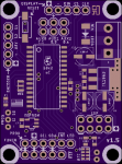
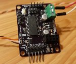
I don't have any experience with CANbus but that's good info. I soldered the bare minimum and tested the 28x2 with the Murata 16mhz res by sertxd some text once a second (pause 8000). It worked fine at 64MHz so I went all in and soldered everything else onto the board and I2C tested fineWhilst it does seem that there is some issue with crystal or resonator selection when using CAN bus this does seem to be an issue specific to CAN bus and similar high-speed asynchronous self-timed protocols.
For low-speed serial there is a much greater tolerance to timing, in the order of +/-6%, and there should be little need for crystal or resonator control. Even less so for I2C and SPI where the bus runs at whatever speed the master presents.
inglewoodpete
Senior Member
I have not had any problems with resonators in PICAXE or native PIC projects, where async serial is the most (Ie not very) critical protocol.
My only CANbus project uses a crystal with ceramic capacitors for the (obvious) reasons mentioned in previous posts. That one works perfectly too.
My only CANbus project uses a crystal with ceramic capacitors for the (obvious) reasons mentioned in previous posts. That one works perfectly too.
All you ever need to know about PIC clock oscillators and resonators/crystals here:
http://ww1.microchip.com/downloads/en/AppNotes/00588b.pdf
Two pin devices need 'load' capacitors of the correct value
Three pin devices have built in capacitors and the centre pin should be connected to 0V
If using an external oscillator then drive the input pin and leave the output un-connected
http://ww1.microchip.com/downloads/en/AppNotes/00588b.pdf
Two pin devices need 'load' capacitors of the correct value
Three pin devices have built in capacitors and the centre pin should be connected to 0V
If using an external oscillator then drive the input pin and leave the output un-connected