3 digit display using 74HC595

rberkelm

New Member
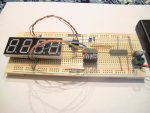
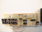
As part of my steep (but fun!) learning curve into electronics, I've tried to implement Westies 3x7 segment LED tutorial using a 4-digit 7-segment LED, but it's not working. The LEDS are flashing 3-digits at once and sometimes 4. The characters being flashed are mostly not numbers, just C's, P's & E's and other odd characters, sometimes just the decimal point. The hardware and code is as verbatim as I can make it. On the hardware side, I have added a 5v regulator to bring my incoming 2 x 3.6v Li-ion supply down to 5v. I'm using an 18m2 chip and a 4-digit common cathode LED from Sparkfun (datasheet here). I've tried all the segments using a battery and resistor and they all check out as per the pin diagram in the datasheet.

On the software side I'm using the code "Three 74HC595 driver code2 - suit 08M.bas" as is (noting the reserved "Shiftout" syntax), but with port B.1 for Latch, B.2 for Sclk and B.3 for SerIn. I can see the code works in debug mode.

There are also a few things about the code that baffle me, despite the well-commented lines (thank you , please keep us newbies in mind!). For example, the values in the lookup table - are they hex? When I Google hex to ASCII they don't come up as numbers at all. Also, how does the command "digout=digout OR $80" turn the decimal point on? (in my mind I'm reading "digout=itself or some hex number...":confused: Same with the mask command "mask=digout & $80" - how does this mask out the leading zero (I presume?)?. Any help to get past my brick wall would be greatly appreciated! Thanks, RayB

PS Thanks to all who have given generously of their time on this forum. I can't begin to tell you how much I've learnt and greatly appreciate it!
 

Attachments

nick12ab

Senior Member
Welcome to the PICAXE Forum.

I've tried to implement Westies 3x7 segment LED tutorial using a 4-digit 7-segment LED, but it's not working.
Can you please provide a link?

The LEDS are flashing 3-digits at once and sometimes 4. The characters being flashed are mostly not numbers, just C's, P's & E's and other odd characters, sometimes just the decimal point. The hardware and code is as verbatim as I can make it. On the hardware side, I have added a 5v regulator to bring my incoming 2 x 3.6v Li-ion supply down to 5v. I'm using an 18m2 chip and a 4-digit common cathode LED from Sparkfun (datasheet [/COLOR]here). I've tried all the segments using a battery and resistor and they all check out as per the pin diagram in the datasheet.
Your breadboard circuit appears to have zero decoupling capacitors. Please add a 100nF decoupling capacitor and a 100µF capacitor on both the input and output of the 7805.

There are also a few things about the code that baffle me, despite the well-commented lines (thank you , please keep us newbies in mind!). For example, the values in the lookup table - are they hex? When I Google hex to ASCII they don't come up as numbers at all. Also, how does the command "digout=digout OR $80" turn the decimal point on? (in my mind I'm reading "digout=itself or some hex number...":confused: Same with the mask command "mask=digout & $80" - how does this mask out the leading zero (I presume?)?. Any help to get past my brick wall would be greatly appreciated! Thanks, RayB
The OR $80 turns on the decimal point because it sets the most significant bit to a 1 which makes the decomal point turn on. The values in the lookup table won't make sense because they are the segment patterns to determine which segment will be on and which segment will be off when the data is sent to the display.
 

westaust55

Moderator
The project I presented has thee discrete/separate 7-segment displays each drive by its own 74HC595 with the three '595 chips cascaded.

From the photo and display Datasheet you have a single 4 digit display module with common a ode digits intended for multiplexing and are using a single 74HC595 and there are no signs of transistors for multiplexing.

The options are to add more '595 chips for a cascaded shift register with discrete digits (no common anodes) or some transistors (eg BC327) to use multiplexing and then modify the code to suit. Based on what you have, the multiplexing way seems the way to go.
 
Last edited:

Hemi345

Senior Member
It looks like the 18M2 is also missing the download circuit resistors. At least put a 10K to ground on the serin pin (pin 3) or goofy things can happen.
 

rberkelm

New Member
Thanks guys for pointing the way forward. I'll have to do some reading on multiplexing. Sofar it's a foreign concept but I remember seeing some posts on it so will do some digging. Thanks Nick12ab for explaining the bits of code - helpful! And Hemi 345 for pointing out the missing download circuit resistors. I'd had actually just removed the download circuit for the sake of a clear picture.
 

westaust55

Moderator
To achieve multiplexing there are two options:

1. Add three transistors (eg BC327) directly driven by 3 PICAXE outputs. Needs three more PICAXE IO pins.
Put a 1 kOhm resistor between PICAXE and transistor base. Transistor emitter to 7-Seg common anode for a digit and transistor colelctor to the LED anodes. Finally LED cathodes to the 74HC595 outputs.

2. Add a second 74HC595 shift register cascaded with the first and use that to control the three transistors. An extra chip needed but no more PICAXE IO required.
Put a 1 kOhm resistor between outputs on 74HC595 and transistor base. and rest of connections as above.

For multiplexing the basis is to put the anode data (which segments to be on) out in the 74HC595 for a given digit and then turn on the transistor controlling the common cathode for that digit. Then using this technique each digit is turned on briefly in sequence and rely on persistence of vision (POV) while the other digits are energised in turn.

For option 1 above, as the 74HC595 has a latching output scheme you can:
1. Clock out the new data into the 74HC595 but do not pulse the latch,
2. Turn off the transistor corresponding to the previous digit,
3. Pulse the 74HC595 latch pin to move data to the ‘595 outputs
4. Turn on the transistor corresponding to the new digit to illuminate.

This scheme requires more PICAXE time just to keep changing the data than a static scheme as per my original 3-digit 7-segment display project. Other chips such as the SAA1064 and MAX7219 do the multiplexing within the chip which reduces the programming requirements on the PICAXE – see other Getting started tutorials I have posted for information on these other chips.

Certainly try the basic multiplexing scheme first with the PICAXE chip doing more of the processing as it will stand you well in future to understand about such display control schemes.

EDIT : corrected transistor type above to correctly reflect the common anodes not cathodes for long term accuracy if others read again.
 
Last edited:

rberkelm

New Member
This is definitely raising the bar a few rungs for me, but I'll give it a go. Thanks for the detailed explanation!
 
Top