28x1 and WS2801 Hack

xtech007

Senior Member
Morning all!
With Christmas around the corner wanted animate a bit my front yard!
Nothing insane just different.

I have play a bit with this combinations of picaxe and the ws2801. Code is more or less sorted out but today is more on the ws2801 side.

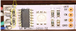
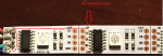
I have a ws2801 led strip with 32 rgb leds (5050) what I would like to do is seperate each module further to cover more area. Cut a few and resolder but no luck. Also noticed that at the first module it has 2 extra resistor that the others don't have!

Anyone can help me would be appreciated!!
http://youtu.be/KURC8_Xk76U
 

hippy

Ex-Staff (retired)
You are effectively only extending the existing PCB tracks so it should work. It could be a timing issue introduced by lengthening the tracks but if the initial feed wires work one would expect the same to work further down the line.

Check you have continuity, no dry joints or shorts. If you have fluorescent lights or anything else which might be causing interference try turning those off. Have you checked voltage is getting through to the extended section ? If you have a scope compare the signals coming out of the first section going in to the second.

And of course check your program is actually controlling the LEDs in the extension !

Perhaps post close-up photos so members can give their opinions.
 

xtech007

Senior Member
will do!

Mr.Hippy tnks for the clues!
I did ck voltage on the side of the new extension while runing the program
+ to G= 5.1volts
Ck to G= 2.34 volts
Sd to G = .51 to .08 volts
But RGB's would not light up. :(
Here is a better picture of the resistors I mentioned earlier at the original joint.
Also tested on another strip without mods and it works fine.
 

xtech007

Senior Member
can not post pictures.

Humm.
App on the iPhone 6 for the forum crashes every time I try to add a picture or video. anyone else with this issue?

Will try again when I get home.
 

hippy

Ex-Staff (retired)
Here is a better picture of the resistors I mentioned earlier at the original joint.
Those are probably just a distraction and not part of the problem. There were not any resistors between one LED module and the next so there should not be any need for them when simply extending the connections between LED modules.
 

xtech007

Senior Member
Mr. Westaust!

Yes, I have read many times the post, in fact my code is based on your program. Only that this one operates 32 leds.

But I think this one might be related to wiring..

Your suggestion are always welcome!
 

hippy

Ex-Staff (retired)
I would guess those resistors are simply to pull-down the clock and data lines so the modules don't accidentally flash or turn the LEDs on when power is connected when the control lines are floating.
 

xtech007

Senior Member
Good Point!

Good point!
I resolder the connections even with shorter extensions and still no luck.
Even with less modules instead of all 32.

Will search the wed if anyone have done something different.
Maybe provide power and ground to each module separately and maybe caps at power lines!

Any comment will be appreciated!
 

Technical

Technical Support
Staff member
Have you actually tested your code on an original (uncut) strip? Get it working on that first before worrying about the extended strip.
 

hippy

Ex-Staff (retired)
Separating the modules and joining them with wires should have worked so; if it's not poor soldering, dry joints or shorts, it's not broken or crossed-over wires then perhaps the modules themselves have become damaged.

How did you separate or cut the modules ? It could be that the PCB tracking on the modules has become cracked or otherwise damaged. Perhaps the extended part took a static shock.

I would say the best approach is to check all the signal paths, out of the PICAXE, into the first section, out of that section, into the second, and out of that as well. That may help identify where the issue lies. You would really need a scope or logic analyser to check the clock and data signals.

You could try separating the last LED from the currently working module, jumping wires to that, to see if that works or stops working. It may be you just got unlucky doing it the first time.
 

westaust55

Moderator
It is certainly not immediately clear why the separated modules are not working.
Can you provide a photo for both side of the boards with the first couple of WS2801 modules.

Have you tried with just 1 or 2 separate WS2801 modules?
 

xtech007

Senior Member
sucessful attemp!

Hi all again!!
Finally some free time, weekend is here!!!
I was able to test and re-solder my connections but also decided to re-solder the original points due to a bit motion on the lines and darn thing would flicker for its life!

That fixed the flickering, but not the other half that would not turn on.
Was tempted to power each module with its own 5v, cap, and ground.
But then it occurred to me why not remove both ends that are differnt to the other, was going to cut each module anyways!

Well darn title bugger worked!
At first with the 3" extention and then after with 1 foot long extension!
Re-attached the original ends and it failed again.
So, away with the modules at the ends!

Here is a video with extensions:
http://youtu.be/vD0jwX6Ncgg
 
Top