24V AC to 5V DC

lbenson

Senior Member
@ lbenson. ---you do not appear to have a current limiting resistor on the input of the opto's in post 18.
Yes, thank you--I had noticed the presence of one in SAborn's circuit, and went back and found it in other versions of mine. I will replace the image and note your spotting of the problem.
 

pilko

Senior Member
Yup - that's the basic solution. Perfectly adequate as long as the PICAXE and the 24V have a common GND.

I would suggest that if implemented as shown you would subject the LED to 34V reverse bias and it would not last very long...

I would move R2 upstream of C1, so that R2C1 form a low pass filter to help suppress spikes from relays etc.

Possibly make R2 and R3 10 times bigger (820K, 100K) if there is any possibility of applying 24V AC without having +5 on the PICAXE. You could of course then make C1 10 times smaller.

Note to self: figure out how to draw and attach quick schematics!
My LED's have lasted several years so far.
This is what happens if you move R2 upstream of C1.
 

Attachments

Armp

Senior Member
My LED's have lasted several years so far.
I would think then that you may have used 'bipolar' or 'AC' LEDS. ie 2 LEDs in parallel in a single pkg. Typical LEDs will breakdown at 5-7V reverse bias, and with 2K load would suffer relatively high power dissipation and short life.

This is what happens if you move R2 upstream of C1.
Sorry for the incomplete configuration. My R3 goes to a 4.7V zener to GND. The logic takeoff is then from R3/zener junction.

Moot point anyway as I now use optoisolators on all systems.
 
Last edited:

premelec

Senior Member
contact 'leakage' considerations

@EGj In post #29 you indicate the signal you are going to use is HIGH OFF and LOW ON - this indicates you are across the Tstat contacts rather than at the place they deliver voltage to. Are the thermostats mechanical contacts? Anyhow you need to determine how much current or voltage drop makes the system register a 'closed' signal - so that your measuring device does not make the system think a Tstat is on because of your isolator current etc. This current / voltage varies a great deal depending on what controls are being operated . If you can get to the place the Tstat switches the voltage to that will be a lot more tolerant of additional loading by your measuring circuit. On the other had a few milliamps to an opto may not bother anything and if you need the voltage to stay high you can use a zener diode in series with a resistor to a bridge to LED in opto instead of just a resistor - Anyhow you are well on your way to finding out what will work...
 

Armp

Senior Member
Anyhow you need to determine how much current or voltage drop makes the system register a 'closed' signal - so that your measuring device does not make the system think a Tstat is on because of your isolator current etc.
The typical Honeywell motorized zone valve, which is what many thermostats are connected to, is rated at 24V, 0.32A, 60Hz. Got one sitting here on the bench.

I would say it takes all of that 0.32A to get it to start moving. So I'm sure even 100mA would not cause it to budge.

Just looked - my transformer is rated at 24V, 4A for a 3 zone system.
 

premelec

Senior Member
variations...

@Armp - yes the direct mechanical motor actuators are certainly no problem and have anticipator resistors in the Tstats for high current - however a lot of much smarter electronic controls are appearing - I use TACO ESP [now re-named something else] zone valves that have super capacitors in them to shut when power is taken off - I used to use White Rodgers driven both ways types and I know the driven Honeywells well. I don't like how noisy the TACOs are but they've been reliable... They all fail shut when the power goes off and a friend lost 7 solar collectors when power failed and the drainback valves shut and no one was there... froze and split the pipes in the collectors... shoulda put Vodka in those collectors... Happy Heating season to ya!

BTW the 100 ma won't get the ZV moving but it likely will burn out opto LED :) Hope EGj gets that figured out ok...
 
Last edited:

SAborn

Senior Member
From the information you gave on the thermostat it should work with that opto, although it will be a pulse signal on the output as discussed earlier, and can be filltered in program.
 

premelec

Senior Member
Looking good...

My recommendation would be to put a large value resistor in series with a diode [or bridge] to an electrolytic capacitor of 10uF or so then to the opto LED - filter before you go to PICAXE input pin. That should result in a clean enough input signal to be considered a digital input pin. If you are unsure post the circuit you propose here and I'm sure you'll have comments...
 

Dippy

Moderator
I'm not sure if EG has understood previous posts...?

Why do you think that Opto is wrong?
(Personally, I'd have gone with standard transistor output , but Darlington prob OK).


Save the code-load and do a minor bit of hardware.

Maybe something like this?
It will add a little delay and this is adjusted by the R1, R2, C1 values.
You may need to play with the values - ideal job for breadboard.

You will have to calculate/breadboard the values.
You will have to calaculate the R3 value to suit your AC voltage and the device parameters.
 

Attachments

SAborn

Senior Member
Why not just do the filtering in code, to me it is so simple, just use count and if there is a frequency (60 hz) then the count will be above zero so the input is high and if the count is zero than the input is low.
A count over 20ms+ should be all that is needed to read a high or low on the input.

Hardware is fine but we have a micro with built in functions so why not just use them to one advantage and eliminate the hardware.
 

Dippy

Moderator
Do whichever you, or more importantly, the OP is happy with. I've got not no preference,
Either way amounts to a just a few minutes of work and informs OP of the basic (no pun) options and how easy it is :)
 

Armp

Senior Member
A bit OT

Maybe something like this?
It will add a little delay and this is adjusted by the R1, R2, C1 values.
Dippy - what do you use to generate quick schematics as jpgs?
I always get stuck when trying to answer this sort of question by my lack of software to generate them easily in jpg format.
 

eclectic

Moderator
Dippy - what do you use to generate quick schematics as jpgs?
I always get stuck when trying to answer this sort of question by my lack of software to generate them easily in jpg format.
Possibilities.

1. A free schematic program (Express/ Diptrace ........)

2. Then screen-capture using for example
Vista / Windows 7/ Gadwin .....

e
 

hippy

Ex-Staff (retired)
... or even create a GIF / JPG template file with common components included, use any graphics editor, copy and paste components, draw lines for tracks.

Pen, paper and a scanner is also an option.
 

geoff07

Senior Member
I don't know what Dippy uses, but I use Eagle and export png files, which are widely compatible but better than jpg for line drawings. PNG is a patent-free alternative to GIF files, and is lossless. If you want to tweak or convert the images later, you can use The GIMP.
 

Armp

Senior Member
Thanks for the suggestions.
I had previously tried Diptrace but couldn't get to jpg.
Then I did the template + Photoshop - big and clumsy.

I've downloaded Gadwin - that looks very good! Captures Diptrace OK, but can't paste into a forum post? Guess I have to save it as a file then insert? That's workable.

Pen/paper/scanner looks like the winner so far :)
 

Dippy

Moderator
That was a simply Print Screen from Labcenter Proteus Isis (it's got PICAXEs).

Here are the output options.

And an example PDF (of a circuit that didn't work).
I've struggled with a couple of basics and I won't say it's flawless, but I find it better than any other CAD mentioned on this Forum. I prefer it to the multi-thousand quid Orcad which I have been using at work. I've transferred everything to Proteus now.
Databasing of components, Gerber reviewing and panelisation... I was confused to start with but now I've got the hang of it I find it excellent. And the graphics card options and 3D rendering makes the others look a bit feeble.


And it's got some PICAXEs... including the ever-confusing-for-some download socket.
Starts at £150.
 

Attachments

Reloadron

Senior Member
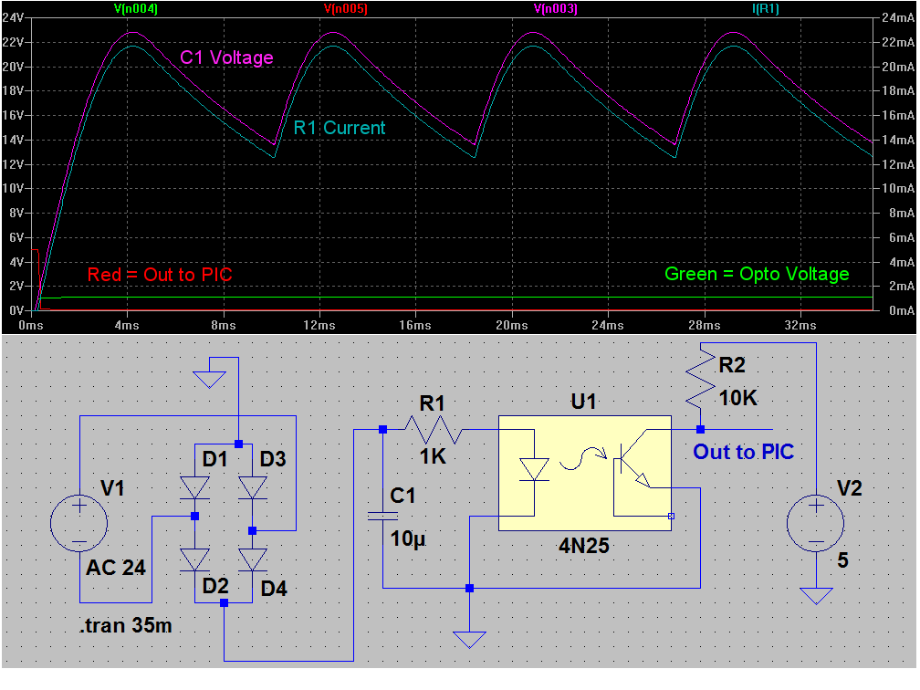
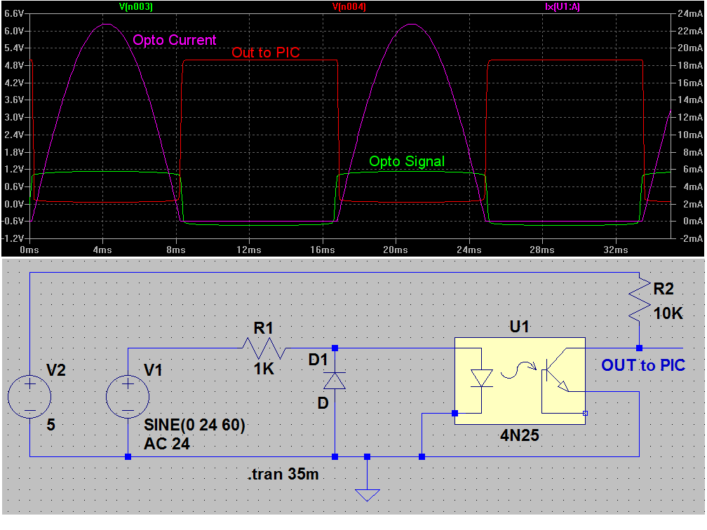
Being real new here I found this to be an interesting thread. What to do with an AC waveform when you want to feed it into a PIC? I guess as pretty well covered there are a few options. Either use a pulse input or use a DC level. I made a few little simulations with circuits that revolve around what was posted here.


Hopefully the images loaded as from work and our servers things don't always work. :(

Anyway, I labeled the traces. Given a choice I would likely use the full wave bridge circuit. A tiny 200 PIV 1 Amp bridge can be had for about a buck or two.

Ron
 

premelec

Senior Member
My preference

I prefer to put a current limiting resistor BEFORE the bridge JIC diodes short etc - and use it to filter rectified voltage to capacitor as well. It's easier on the diodes too... Yes... most transformer windings will also limit current [unless they are superconductors...].
[JIC = Just In Case]
 

Reloadron

Senior Member
Boo hoo ... you didn't simulate my circuit. :(
I feel really left out. I'd better go to the pub.
This weekend. :)

What was done was done in haste at work. Love the holiday season, nice and quiet around here. After work...then the pub, or two, or three.

I also thought about current limiting upstream but didn't have time to mess with it.

I figure the m,oral of the story is what was mentioned all along. You can feed the PIC pulses or hi low logic. :)

Ron
 

Dippy

Moderator
Oooh Evil Genius, you've lived up to your name :)

You've finally got a solution the PICAXE collective brain and then used a competitor - that's Evil Genius!
But maybe you should have kept quiet about your Ardweeny?
Perhaps a real Genius wouldn't have mentioned it - with future design projects in mind.
Some PICAXErs may think twice about helping you in future...

But I won't tell anyone, youre secret is safe. Happy Christmas


Ron. Thanks, but no need to do it just for me. I was only kidding about feeling left out, and I know it works as I've done it before - albeit with an AC opto. There were several methods to do this project and I reckon all were comprehensively covered, so well done to all.
 

SAborn

Senior Member
I often see electronics as a much bigger field to just picaxe, and also see this as a perfect example of one learning how to use supportive components to the picaxe, even though EG has jumped the fence to a different platform, it has also created a discussion to a problem that others may have learnt from, so all in all not everything is lost and if nothing else EG has gained knowledge he can take away as a positive.

As much as i support Dippys comments, it is also important to understand that everyone should be free to tap into the collective knowledge base of members regardless if it is picaxe based or not, as i see it just as important to understand the supportive components as the picaxe itself.
 

Dippy

Moderator
I was, in fact, having a little Christmas jovialisation ... albeit with a gentle ribbing :)

Personally, I have no probs with it. A good, albeit long, discussion is informative. It was the irony of the final comment plus username that made me titter - especially as I had just been reading the "PICAXE Popularity" thread.
 

premelec

Senior Member
support forums...

I was taking this as evidence that the Arduino forums weren't as supportive and friendly as this one - which has seemed to me for many years to be incredibly useful and tolerant of all sorts of questions - and a main feature to recommend PICAXE products. I still wonder how Nesbit is doing :) [did I remember the rabbit's name correctly? ...]

Thanks to everyone for being so helpful to experienced and newcomer folks it's what keeps people learning what is a very extensive and diverse field of electronics and problem solving approaches... Keep up the good work!
 
Last edited:

eclectic

Moderator
Nesbit is correct,
named for the Scottish Folk hero
Rab C. Nesbitt.

The only BBC programme, as far as I know,
to provide subtitles in English.

e
 
Top