20x2 Resetting and acting wierd when Input C.3 goes low.

sodeaf

Senior Member
Hey Guys.. You have been a great help in the past.. and I know I will scolded for not supplying diagrams and code at this point..

But I wanted to know if anyone has any quick tips to why I am having this issue..
I am using a 20x2.. I have it wired too a Max202 Chip using Hserin - Hserout commands and it works well. As well Using Hspi to talk wiht Max7219 which works great as well.
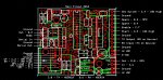
C.0 - Max 202
B.6 - Max 202

C.1 - To input of Max7219
B.7 - Clock to Max 7219
B.1 - Load for MAx 7219
B.5 - Spi Input not used Tied 10K Low

Serial in and out connect to 3.5mm jack with resistors.

C.2 - C.7 , B.0, B2, B3,B4 all Tied High 10K then to Push button to Ground (each has there own resistor and button) as well as .1uf cap to ground )

The program runs great.. If I toggle inputs other then C.3 everything is fine. I am currently not using C.3 in the program but for fun I pushed the button and It "Locked up the picaxe" and if i repeatedly hit the button the picaxe will
restart for the Max7219 re-initializes. All other inputs are fine.. Why is C.3 acting this way?

If I change dirsC = %00001011 (c.3 to an output) of course it no longer reacts to the input and everything if fine, but if it is set to an input and the button is pressed it freezes then resets.

Is C.3 somehow connected with Hserin-Out or Hspi ? Should i not use this pin at all?
(Board has 100uf cap on power and .1uf cap at +/- at 20x2) All proper .1uf caps are used for Max202, Max7219 has 10uf cap and 22nf cap at its power terminals)

Any suggestions.. I could put together a diagram but it is hooked up properly and the Max202 is working perfect as well as the Max7219..

Thanks

Steve
 

inglewoodpete

Senior Member
The C.3 pin has other lives - as a reset pin. and as the programming pin for the bare PIC. So you need to take care with what you connect to this pin.

Please post a circuit diagram and a photo of your circuit and forum members should be able to help you further.
 

sodeaf

Senior Member
Thanks got taking the time to reply. I tested the input on the scope right at the 20x2, and did not see any abnormality. But I will look it over closely.

I will swap chips and see if there is any change , will keep you posted.

Steve
 

Goeytex

Senior Member
You may want to put the scope on the Picaxe V+ Pin and look for a voltage drop
or a low going spike. Set the scope to trigger on the falling edge. Then do whatever
it was you were doing to make the Picaxe reset.

Another test may be to use the disablebod command and see what happens.
 

sodeaf

Senior Member
OK,
Well I used the scope and found no problems.. I double checked the traces on the board 15 times.. I removed everything from the board, the max 202 and the max7219 and when pin C.3 goes low (I tap the button a bunch of times fast) the 20x2 freezes then resets, just freezes or just resets 90% of the time its right away.. sometimes it takes 10 sec or so.. I tried everything to correct this.. Finally I just cut the trace (4mm long from 10K to Pin) to pin C.3 and soldered a jumper from the 10 resistor that was connected to C.3 and connected it to B.4, changed c.3 to an output and reassigned the program to look for B.4 instead. and it works great. So this rules out trace problems to C.3, for the circuit works great on B.4. I tried 2 different 20x2 chips with the came result. As i type this the 8 segment display has counted up to 11 minutes so far and I keep tapping the button with no issues.

So I don't know if this is an issue with the 20x2..or I am just crazy.. Maybe if anyone can duplicate this with their 20x2 and see.. I guess it would have come up by now if other people had issues, but I am stuck for an answer. I will solder up another board identical to this one and try it again next week and see if for some reason its the board.. But I cant see how..

The board is powered by 12VDC and I am using a DC-DC converter to 5VDC. 10uf Cap before Converter (12VDC) and 100uf after (5VDC). as well .1uf from 5vdc-ground and 12vdc to ground all located close to converter.

Thanks

Steve


Thanks

Steve
 

hippy

Ex-Staff (retired)
So I don't know if this is an issue with the 20x2..or I am just crazy.. Maybe if anyone can duplicate this with their 20x2 and see.. I guess it would have come up by now if other people had issues, but I am stuck for an answer.
As you say; if this were a systemic problem we would have had more cases of it but it does seem to be unique to your configuration. There's nothing special or particularly different about C.3 than any other I/O pin so there should not be a problem.

Without the program code, circuit diagram and photographs of the assembly it is hard to say exactly what the problem is. That it works with B.4 does not discount there being an issue with the code itself and that's what my gut feeling is telling me. It's easy enough to post the code so I would recommend doing that; there's nothing to lose and everything to gain.
 

sodeaf

Senior Member
Layout.jpg

Thanks guys for the input... I appreciate it... I have put attached the image of the board i designed.. It has been Printed.. I had the setup running fine on the breadboard, but didn't really test the buttons at that point.. For I thought it was a no brainier. I am using RJ45 connectors from on board to the other. The other being the Max7219. I am using Standard store bought 3 ft Cat5e Cables. I thought at first there was interference and maybe I should swap to Cat6E, but considering it works just fine on B.4, I cant see that being the issue and the Max7219 works great. The buttons are on the Max7219 Board.. Will post picture soon.. As well as code.. and full schematics if necessary.. I highlighted all connections that are involved with C.3, There is a 5 pin 10K Resistor Array (Bussed) pulling input high. When I test the input via scope the signal has next to no noise measuring at 1ms its a straight line on the scope. If I test the Serial input pin.. It is very noisy. I used a .1uf decoupling cap to clean it up but the problem was still there so I removed the cap from that pin. Before I connected to B.4, B.4 went straight from the 20x2 to the connector on the board. I cut the trace between the Resistor array and C.3 Pin and soldered a wire from the Resistor array to the B.4 Pin. So B.4 is using the exact same materials and traces as the C.3 was.

Thanks

Steve
 

boriz

Senior Member
"...If I test the Serial input pin.. It is very noisy..."

Me thinks there's you problem. So, why is it noisy?
 

sodeaf

Senior Member
Yeah I understand your point.. But when I used a .1uf cap to ground on the serin pin the noise was gone and everything still worked fine other then input C.3

I have never tested other Serial Input pins on other projects so i don't know if the amount of noise in the signal is normal and below and limits that would cause an issue.
I will test that tonight on the breadboard to see if there is any comparison. If that's the case, I will cut the trace near the pin and redo something temporarily to see if it is picking up noises from the traces on the board.
 

russbow

Senior Member
I have never put a cap on the serin pin - not good for input waveform.
Has the pin the proper input resistors, or at least tied to ground?
 

srnet

Senior Member
Yeah I understand your point.. But when I used a .1uf cap to ground on the serin pin the noise was gone and everything still worked fine other then input C.3

I have never tested other Serial Input pins on other projects so i don't know if the amount of noise in the signal is normal and below and limits that would cause an issue.
I will test that tonight on the breadboard to see if there is any comparison. If that's the case, I will cut the trace near the pin and redo something temporarily to see if it is picking up noises from the traces on the board.
Well it does depend on how much noise you actually mean, there will always be noise in electrical circuits.

Unless your running the circuit at absolute zero in which case the universe has probably ceased.

So how much noise, a few 10s of mV could be normal ....
 

hippy

Ex-Staff (retired)
I have never put a cap on the serin pin - not good for input waveform.
Has the pin the proper input resistors, or at least tied to ground?
Was just about to say the same; the 22K is there but I can't see the 10K. It's better to post a circuit diagram ... and your source code ;-)
 

Technical

Technical Support
Staff member
We agree, the missing 10k means it is lucky to work at all, as serin can float.
Simply solder a 10k on the the back of the programming header, across the two pins 'serial in' and 'ground'.
 

sodeaf

Senior Member
The noise is not that substantial. and there is a 10K to ground. Beside the 22K on the right there is another 10K array to ground, one is for the serial input pin. I am currently soldering up another board to see what happens.

Thanks
 

inglewoodpete

Senior Member
To test the DC characteristics of the serial in circuit, remove/unplug the PICAXE chip and the programming lead. Measure the resistance between the serial in pin (Leg 2) and 0v (Leg 20). It should be around 32 kohms.

Also, is the circuit stable when the programming lead is connected, but unstable when the lead is unplugged?
 
Last edited:

sodeaf

Senior Member
OK, I am totally confused.. (Keep in mind I am 100% self thought at this, and by reading this forum and the internet have gained what little skills i have in micros, So I am not educated in every aspect..)

I have torn this board apart down to the bare minimums just to run the max 7219 and 2 switches (Up and down). All the connections to Max7219, SPI, Load, Clock, power, ground, and up and down are using an RJ45 on both boards.. Connected with a cat5e cable. (3 ft)
I used pin 4,5 for the buttons for it was the blue twisted pair in the cat 5, keeping them together i guess. When I hit the up button connected to the 20x2 C.3, the 20x2 freezes or resets as previously mentioned, this only happens on C.3, I have tried it on B.4 with no issues.. although once and awhile the Max7219 would do funny things with b.4 but it would not interrupt the 20x2. If I took a jumper and connected one end to ground and tapped directly on input C.3 nothing would happen, everything works well.. So I started to look at the 8 segment display board to see if the issue was there. When I was grounding pin C.3 with jumper I had my scope connected on the 7219 board to the output pin of Up switch, and other lead to ground. And the signal was reacting properly.

So then I got thinking, Maybe there is interference in the Cat5 Cable. Because I only get this issue when the signal travels from 7219 board threw cable to 20x2 board. I stripped back the outer coating of wire 1" from end connected to Max7219 board and cut the solid blue wire (up wire to C.3) When I hit the button the the 7219 board nothing happened, so there was no board interference. But if I tapped that solid blue wire to ground I got the same result.. The 20x2 froze.

Last but not least..

I decided to cut out the .1uf cap connected between c.3 input and ground. And the problem went away.. I cannot get it to mess up no matter what. It has been flawless with more then 500 pushes on the up button. Now I know it is hard for you guess what the issue is.. and I will post code and schematics to Max7219. I left the cap in that connects to C.2 and Down button from max7219 board, that input works fine. I have made 3 boards prior to this and all of them had the same issues, so its not chip or board specific. they all did the same thing. I also bought Cat6 cable with same results. it all comes down to the cap on pin c.3, but with cap in and connected to B.4 the issues were not there.

Overall..

Pin C.3 does not like .1uf cap tied to it and ground when being used as simple ground input and tied high threw 10K. I will continue to try and find out why this happened, and if anyone has any input would be great..

Regarding the Serial input pin.. I tested the Serial pin on my Axe091 board and they were identical. This problem was happening with or without the programming cable plugged in as well.


Why would a simple cap do this?

Thanks

Steve
 

sodeaf

Senior Member
#Picaxe 20x2
setfreq M16

dirsC = %10100011
dirsB = %10111111 '1 indicates output, 0 indictaes input


symbol TournStart = PinC.4
Symbol TournUp = PinC.3
Symbol TournDn = PinC.2
Symbol Load = B.1 ' Register addresses for the MAX7219
symbol decode = 9 ' decode register; specify digits to decode
symbol brite = 10 ' intensity (brightness) register; 15 = 100%
symbol scan = 11 ' scan-limit register; specify how many digits
symbol on_off = 12 ' 1 = display on; 0 = display off
symbol blank = 15
symbol level = 12


SETTIMER T1S_16 'Setup Timer to 16MHZ for 1 Sec
TIMER = 0 'Clear Timer to '0'


' -----------------------------------------------

init:

hsersetup B19200_16, %000
Pause 500
hspisetup spimode00,spifast ' set up hspi
output b.7
pause 500

hspiout (scan,7) ' set scan limit for digits 0-3 2 gives us 3 digit display
pulsout load,1
hspiout (brite,level) ' set brightness to 5 (15 = 100%)
pulsout load,1
hspiout (decode,%11111111) ' set BCD decoding for digits 0-7
pulsout load,1
hspiout (on_off,0) ' turn display off
pulsout load,1


pause 2500

hspiout (8,blank) ' 8th Digit from left "7"
pulsout load,1
hspiout (7,blank) ' 7th Digit from left "6"
pulsout load,1
hspiout (6,blank) ' 6th Digit from left "5"
pulsout load,1
hspiout (5,blank) ' 5th Digit from left "4"
pulsout load,1
hspiout (4,blank) ' 4th Digit from left "3"
pulsout load,1
hspiout (3,blank) ' 3rd Digit from left "2"
pulsout load,1
hspiout (2,blank) ' 2nd Digit from left "1"
pulsout load,1
hspiout (1,blank) ' 1st Digit from left "0"
pulsout load,1

hspiout (on_off,1) ' turn display on
pulsout load,1

Main2:

Clock:
b6 = timer / 60
b7 = timer //60
if b6 > 9 then let b8 = b6 dig 1 else b8 = blank endif '10th minute
if b6 > 0 then let b9 = b6 dig 0 else b9 = blank endif 'Minute
if b7 > 9 or b6 > 0 then let b10 = b7 dig 1 else b10 = blank endif '10th Second
if b7 > 0 or b6 > 0 then let b11 = b7 dig 0 else b11 = blank endif 'Second


ClockDisplay:

hspiout (4,b11) ' 4th Digit from left "3"
pulsout load,1
hspiout (3,b10) ' 3rd Digit from left "2"
pulsout load,1
hspiout (2,b9) ' 2nd Digit from left "1"
pulsout load,1
hspiout (1,b8) ' 1st Digit from left "0"
pulsout load,1

goto main2
 

sodeaf

Senior Member
main.jpg

Well that is it.. You have everything.. Hahah PLEASE HELP!

I guess I just want to make sure i goofed and I don't need this cap.. There has to be a reason.. I don't know move forward not knowing why this happened..

Thanks Guys
 

premelec

Senior Member
I haven't fully followed this thread - you've got a complicated project going there! Anyhow note that every wire has some capacitance and inductance and that when you charge or discharge a capacitor it generates a current pulse. If things are close to unstable a .1uF capacitor pulse into the power source could disrupt your circuits. Cat 5 cable has capacitance between the conductors. I gather you are learning and trying to explain - if you have an oscilloscope look for small pulses on the power bus when things aren't working... Electronics is an art as well as a science and each layout is different. Good luck with it!
 

srnet

Senior Member
Surprised it works at all really.

You are using SPI out at 16Mhz in fast mode over 3 feet of un-balanced cable, with no terminating resistors at either end that I can see.

Category 5 is balanced cable, for it to work properly you need a balanced signal on each pair, say a signal and ground, yet you appear to have c.3 and c.2 on the same pair, so I would expect any signal on c.3 to be coupled to the signal on c.2 and vice versa.

And in addition, the signals on other pins could couple quite nicely into the c.3 also.
 
Last edited:

hippy

Ex-Staff (retired)
There's nothing special or particularly different about C.3 than any other I/O pin
I might have to retract that. For a native 18F14K22, C.3 is the PGM pin, and I'd guess out of spec voltages could potentially cause issues. With a 6-foot run from main board to display and back again there's the possibility of some induced transients on the pin. That you get occasional problems with the MAX7219 suggests that not everything is okay.
 

sodeaf

Senior Member
The funny thing is.. I could not pick up any weird spikes or anything with the scope.. But that doesn't mean they were not there... I have been trying to break this thing for hours.. Or I should say.. try to get it to mess up.. But its working beautifully. I removed both .1uf caps from c.2 and c.3.. just to be sure..

The MAx7219 is working great as well as the 20x2.. C.3 must have been seeing some odd spiks in the line and went into program mode? The 20x2 was reacting that was at least..

I honestly knew i was taking a gamble when it came to using the cat5 cable.. I just hate making cables.. and for the cost of the cat5 cable with ends, and a couple rj45 connectors for the boards, I couldn't beat it. I will know for next time. But for now.. everything seems to be OK.. I will know more as I build on the RS232 code and add all the goodies..

Thanks for taking the time to read this post.. I really appreciate it.. If anyone has any other input please feel free.. For I am eager to learn...
 

inglewoodpete

Senior Member
I might have to retract that. For a native 18F14K22, C.3 is the PGM pin, and I'd guess out of spec voltages could potentially cause issues. With a 6-foot run from main board to display and back again there's the possibility of some induced transients on the pin. That you get occasional problems with the MAX7219 suggests that not everything is okay.
hippy, It 's getting quite confusing. I suggested that pin C.3 was the reset/programming pin in post #2. This was corrected by Technical: C.6 (leg 4) is the MCLR/Vpp pin on the 20M2. (I had mixed my 08M2/14M2 and 20M2). So C.3 should behave "normally" as far as pins go.

I'd put my money on misuse of the Cat 5 cable wires: crosstalk between hspi signalling and steady-state input.
 
Last edited:

sodeaf

Senior Member
"I'd put my money on misuse of the Cat 5 cable wires: crosstalk between hspi signalling and steady-state input. "

Trust me I feel bad and I do sincerely apologize to the Cat5 Cable world.. I will never do this again! hahaha

I will try and hard wire the 2 boards using 8 x 22 Awg stranded copper. All loose single wires.. and see if the problem still there.. I will install the caps back in the line.. I am now curious to see if it really is the Cat5 Cable.. I tried using cat6e.. which is supposed to have some sort of shielding between each pair of wires.. I honestly feel very stupid for not asking you guys your input on this before i designed the boards.. I did not think of it in depth.. I thought it would be fine.. 4 pairs of twisted wires.. and for what I was doing i thought it would work.. By the time I had the whole project breadboard and working.. It was a mess of wires going in every direction.. I had the 7219 mounted on the opposite side of the work bench and 3 different breadboards all connected with jumpers.. and it worked great.. (although i did not include the .1uf caps in the breadboard design) I added them when creating the PCB as an insurance to get rid of any noise in the line for another project I was working on needed the cap to keep the input more stable.. so I thought hey why not include one on all inputs.. WRONG!

I will keep you guys posted.. You are all probably shaking your head at me.. I thank you again.. for all your input.. In the end its a great learning experience.. I could not imagine doing this for a living.. I give those guys so much credit.. The amount of variables you have to look at must be insane.. The program is probably 10% of the project.. the rest is trying to design the board and connections 100% to insure everything works properly.. Where in my case.. I look at the program part to be the Hardest and didn't give much thought to the overall all connections and pcb design..

Steve
 
Top