Hey Guys,
Quick Run Down.. I have been playing with Picaxe for about 4 years and have made many Circuit boards.. Im am certainly at the hobby level.. But have learned a lot over the past couple years and have yet to run into something as crazy as this.
My Latest Board consists of a picaxe 20X2, Max7219 and a 12V to 5VDC 800 MA regulator. I have followed all specs from data sheets. I have used this same set up many a times, but I do keep improving the board adding things here and there. I just received 10 New boards on Friday and spend the the weekend soldering it all up. I loaded the program to do basic tests and everything seems fine at this point. I am using pretty much every pin on the chip.
I have a 20 Pin Molex header on the board, At this point I only have 2 Wires connected 12VDC and GROUND. With the Picaxe running and the 7 Segment display Counting up I plug in a wire to the molex connector and the Picaxe Resets (starts from first line of code, I know this for I have a boot sequence programed that is displayed on the 7 segment display) I thought this was a fluke! The wire i plugged in connects to pin C.6 through a 1K Resistor, as well pulled high with a 10K. Simple Negative (low) input that connects to an off board push switch. The wire i connected is 72 Inches long, the other end is not connected to anything at this point. I could see the program reacting as if the button was pushed, but it doesn't, it resets the picaxe, If i unplug this single piece of wire and the re-connect it resets again and again. If I leave the wire connected and touch to ground the input works on the picaxe, and it does what it should via the Code. But i noticed that if I turn my solder iron or Scope with the 72 inch wire just hanging there, it resets. I am using a bench supply to power the board.
Here is the crazy part.. (I am using the proper .1uf and 1uf Bypass caps, plus 100uf cap all located very close to Picaxe and i have tried about 30 different other combinations, but the original deign has never giving me issues. )
I have put a 20X2 chip on my AXE 091 Bread Board, Connected a jumper from PIN C.6 to board pulled high through 10K.
C.7 is connected to LED Positive on Bread Board
C.4 is connected to board with 10K pull up
This is the complete code minus the symbol setup and Dir setup
Nodata:
Wait 2
high ledout
high alphatrig
wait 2
low ledout
low alphatrig
if tickin = 1 then
goto nodata
endif
high alphatrig
high ledout
wait 10
goto nodata
Now I have Tried this setup using 12V in through the regulator, also tried skipping the regulator and connecting 5 VDC to board after regulator, I have tried using an isolated 12VDC battery.. I get the same results. Even on the AXE 091 Board.
If I take this 72 Inch long 22 AWG wire with one end connected to nothing and the take the opposite end and just touch the lead on the 10K resistor closets to input jumper side the led will stop flashing, (Picaxe will reset) if i connect the wire and after it resets I ground the opposite end the picaxe follows code. Its only when I connect the wire does it make it reset. When the wire is just sitting on bench and I turn my Iron on and off the picaxe will reset. If I remove the wire it wont. But I tried this some thing with PinC.4 and it does not respond to any of this.. as it should, I can tap the wire to it all day with no response, I can turn all my bench gear on and off with no response, when I ground the input it does what it should. PinC.6 well that's another story.
I understand it could be picking up AC Spikes, static and such.. But This seems to be way to sensitive. I Tried changing code and pulling Pin C.6 Low all the time... I get the same result. Is there something I am missing? Please.. HELP!
I have tried several Chips, New ones from a recent batch and Old ones I have had a while. This is mind boggling.
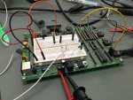
the wire in picture (White) is what causes all this...
Quick Run Down.. I have been playing with Picaxe for about 4 years and have made many Circuit boards.. Im am certainly at the hobby level.. But have learned a lot over the past couple years and have yet to run into something as crazy as this.
My Latest Board consists of a picaxe 20X2, Max7219 and a 12V to 5VDC 800 MA regulator. I have followed all specs from data sheets. I have used this same set up many a times, but I do keep improving the board adding things here and there. I just received 10 New boards on Friday and spend the the weekend soldering it all up. I loaded the program to do basic tests and everything seems fine at this point. I am using pretty much every pin on the chip.
I have a 20 Pin Molex header on the board, At this point I only have 2 Wires connected 12VDC and GROUND. With the Picaxe running and the 7 Segment display Counting up I plug in a wire to the molex connector and the Picaxe Resets (starts from first line of code, I know this for I have a boot sequence programed that is displayed on the 7 segment display) I thought this was a fluke! The wire i plugged in connects to pin C.6 through a 1K Resistor, as well pulled high with a 10K. Simple Negative (low) input that connects to an off board push switch. The wire i connected is 72 Inches long, the other end is not connected to anything at this point. I could see the program reacting as if the button was pushed, but it doesn't, it resets the picaxe, If i unplug this single piece of wire and the re-connect it resets again and again. If I leave the wire connected and touch to ground the input works on the picaxe, and it does what it should via the Code. But i noticed that if I turn my solder iron or Scope with the 72 inch wire just hanging there, it resets. I am using a bench supply to power the board.
Here is the crazy part.. (I am using the proper .1uf and 1uf Bypass caps, plus 100uf cap all located very close to Picaxe and i have tried about 30 different other combinations, but the original deign has never giving me issues. )
I have put a 20X2 chip on my AXE 091 Bread Board, Connected a jumper from PIN C.6 to board pulled high through 10K.
C.7 is connected to LED Positive on Bread Board
C.4 is connected to board with 10K pull up
This is the complete code minus the symbol setup and Dir setup
Nodata:
Wait 2
high ledout
high alphatrig
wait 2
low ledout
low alphatrig
if tickin = 1 then
goto nodata
endif
high alphatrig
high ledout
wait 10
goto nodata
Now I have Tried this setup using 12V in through the regulator, also tried skipping the regulator and connecting 5 VDC to board after regulator, I have tried using an isolated 12VDC battery.. I get the same results. Even on the AXE 091 Board.
If I take this 72 Inch long 22 AWG wire with one end connected to nothing and the take the opposite end and just touch the lead on the 10K resistor closets to input jumper side the led will stop flashing, (Picaxe will reset) if i connect the wire and after it resets I ground the opposite end the picaxe follows code. Its only when I connect the wire does it make it reset. When the wire is just sitting on bench and I turn my Iron on and off the picaxe will reset. If I remove the wire it wont. But I tried this some thing with PinC.4 and it does not respond to any of this.. as it should, I can tap the wire to it all day with no response, I can turn all my bench gear on and off with no response, when I ground the input it does what it should. PinC.6 well that's another story.
I understand it could be picking up AC Spikes, static and such.. But This seems to be way to sensitive. I Tried changing code and pulling Pin C.6 Low all the time... I get the same result. Is there something I am missing? Please.. HELP!
I have tried several Chips, New ones from a recent batch and Old ones I have had a while. This is mind boggling.
the wire in picture (White) is what causes all this...