18M2 pins C.3 & C.4

joe paul

Senior Member
Hi Folks,

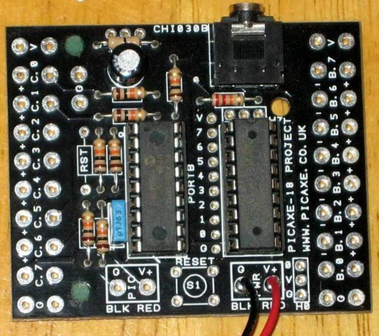
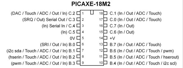
With the 18M2 project board, the manual says: "The connections marked C.3 and C.4 should not generally be used with the PICAXE system. These are used by the PICAXE chip as the ‘serial in’ and ‘serial out’ PC download connection."
http://www.picaxe.com/docs/chi030a.pdf page 5

Can C.3 and C.4 be used as either INPUTS or OUTPUTS in your code? Aside from pins 5 & 14 (power pins), can the rest be used or are some off limits?

Thanks!

Take care, Joe.
 

inglewoodpete

Senior Member
As shown in Manual 1, page 10, both C.4 and C.5 can be used as inputs. The CHI030a board can be quite restrictive when it comes to some pins and it would pay you to check the CHI030a pdf file to see if C.4 and C.5 can be easily accessed.
 

joe paul

Senior Member
Hi InglewoodPete,

Thanks for the help! This is the board.


All the pins are accessible.

So C.3 can be used as an OUTPUT.

Take care, Joe.
 
Last edited:

inglewoodpete

Senior Member
Whoops! Out by one. It reminds me of buttoning up my shirt when I was a kid - sometimes I had a button left over!

You are correct - C.3 can also be used as an output. You have the take into account that it will toggle continuously when you download a new program to your PICAXE. If it does something harmless like flash an LED, then that's fine. However, if it operates a relay or turns on a motor, then that could be a problem. Where ever possible, pin C.3 on an 18M2 should be confined to doing something fairly 'harmless'.
 

edmunds

Senior Member
I have used a jumper for some projects to switch between 'programming' and 'operating' modes on some projects where I needed the pin. Since the pcb is already there for this project, maybe a STDP switch could do the same - middle terminal to C.3, one side to programming connector (not the one on the pcb perhaps) and the other side to your load.

Good luck,

Edmunds
 

joe paul

Senior Member
You have the take into account that it will toggle continuously when you download a new program to your PICAXE. If it does something harmless like flash an LED, then that's fine. However, if it operates a relay or turns on a motor, then that could be a problem. Where ever possible, pin C.3 on an 18M2 should be confined to doing something fairly 'harmless'.
Hi InglewoodPete,

Thanks for the reply and information! I would be using it for a relay, most likely, but when I program the chip, I usually have the project board disconnected from my other circuits. I even have a board I use just to program the chip, then I move the chip to either an IC socket on my homemade board or anther project board. Because most of my toy train projects connect to AC at up to 25 volts, I am leery of ever having my laptop connected to a running project for programming. Takes more time, but I feel safer that way.

Take care, Joe.
 

joe paul

Senior Member
I have used a jumper for some projects to switch between 'programming' and 'operating' modes on some projects where I needed the pin. Since the pcb is already there for this project, maybe a STDP switch could do the same - middle terminal to C.3, one side to programming connector (not the one on the pcb perhaps) and the other side to your load.

Good luck,

Edmunds
Hi Edmunds,

Thanks for the reply and the great tips!

Take care, Joe.
 

joe paul

Senior Member
@Joe,

you may also wish to read this thread about the very same topic of using C.3 and C.4 on an 18M2 for IO purposes:
http://www.picaxeforum.co.uk/showthread.php?28730-18M2-Question
Hi WestAust55,

Thanks for the reply and the link! (and your help on MERG).

I was uncertain and once resolved the issue in my mind, but forgot what I had determined! I need to get back up to speed on the Picaxe, especially with the high cost of hobby products today!

Take care, Joe.
 

joe paul

Senior Member
Hi Folks,

I won't start a new topic since this relates to this discussion. With the DISCONNECT command, would using that command speed up the execution of the code, especially if there are about 30+ lines of IF /THEN statements at the beginning of the program?

Thanks!

Take care, Joe.
 

westaust55

Moderator
I suspect (not tested) that the speed improvement would be minimal.
While the DISCONNECT command changes the firmware execution in that the SerialIn pin does not have to be checked after each BASIC statement, the firmware still has I suspect to test/check a flag each time to ascertain that the DISCONNECT status is active or not.

It might be more productive to review the IF...THEN statements and see if there is a way to change that structure if speed is a crucial topic.
 

joe paul

Senior Member
I suspect (not tested) that the speed improvement would be minimal.
While the DISCONNECT command changes the firmware execution in that the SerialIn pin does not have to be checked after each BASIC statement, the firmware still has I suspect to test/check a flag each time to ascertain that the DISCONNECT status is active or not.

It might be more productive to review the IF...THEN statements and see if there is a way to change that structure if speed is a crucial topic.
Hi WestAust55,

Thanks for the information! Yes, I need to tighten up the code, but that would involve some mathematical operations, but gather that would still improve execution time, although I haven't tested the 30+ lines yet. I think I just need to focus on the program since the circuits connected to the chip are very simple. It has been a while (since 1977) that I actually did tricks with code. I had gotten my head around PEEKs and POKEs with the old Timex/Sinclair BASIC back in 1995, but that ship has sailed!

Take care, Joe.
 
Top