Brokenrecord
New Member
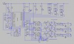
Hey Guys, so I just finished this schematic based around the aforementioned voltage regulator. Any suggestions/corrections?
Thanks
Thanks
Attachments
-
 145.4 KB Views: 21
Bypass caps are installed *in parallel* with the chip, between +5 and ground, not in series as you have them depicted.Wapo,
What do you mean correct the bypass caps +5? Do you mean they should be 5uF? And I do realize that they will not give the full 12v output, however I was just following the diagram provided. From my understanding the LM317 is governed by the equation Vin - 3 = Vout anyways. And since I can't find a 15v source I'll just have to live with it.
Also I have one voltage regulator with 24v in, so to give me a close maximum output I put two resistors in parallel; 4.7K and 10K. Is that correct? And finally I tied the serial outs of the 08m's together so that each one could send they're data to in 7 of the 28X1. I'll be implementing a polling mechanism to acquire temperature data and store it in the eeprom. Does that make sense or is it even feasible?