120VAC Solenoid and 12V fan control

Brokenrecord

New Member
Hey guys, I'm very new to the picaxe scene and got interested in it when I realized I could use a picaxe as a very cheap and infinitely more flexible alternative to a retail greenhouse control system (http://www.4hydro.com/growroom/sentinelEVC1.asp). My plan is to control 3 120VAC solenoids (two for irrigation, 1 for c02) and around six 12V computer fans using a picaxe 28X1 powered by a computer power supply. Before I begin though I'd really like to ask a couple of questions from the experts on this forum.

  1. Can a picaxe run reliably off of a 5v lead from a computer power supply?
  2. Can I control the solenoids directly from the picaxe using this relay http://www.radioshack.com/product/index.jsp?productId=2062478&cp=&sr=1&origkw=reed+relay&kw=reed+relay&parentPage=search?
  3. What safety precautions (other than grounding the enclosure) must I be sure of when working with 120VAC?
  4. What is the easiest way to turn on/off 12V computer fans OR vary their speed?

Thanks for all your help and feel free to ask any questions of me if I haven't clarified things enough
 

atharvai

Senior Member
1) i believe the PICAXE CAN run reliably from a 5V PC supply as that is regulated
2) the relay seems to be 5V maximum. how were u planning to connect the 120V solenoids?
3) isolation of circuit. keep the PICAXE and solenoids seperate even the boards not just by relays. anyone else thoughts on number 3?
4) if u connect the fans directly to PIcaxe they will run at low speed as the max the PICAXE can supply is 5V. PWM is used to vary the speed. try a search on the forum for PC fan or PWM. 28X1 has a different PWM command than the 28X so look that up in manual 2.
This is a good link for PWM on 28X1: http://www.picaxeforum.co.uk/showthread.php?t=10182
u can use the relay u mentioned to just turn on/off the PC fans but not solenoids
thats all from top of my head. I'm sure other forum members know much more detail than me.
 
Last edited:

Brokenrecord

New Member
Well I planned to connect to relay using the "standard MOSFET" circuit from page 23 of Manual 3, but any other suggestions are welcome. The way I understand it is that the relay coil is rated at 5V max but it can switch up to 120VAC. So as long as I can switch the solenoid on and off I'll be happy. My only concern is that the picaxe will be able to drive the relay because it only outputs 20mA (from what i've read). I'm using some very cheap (3$) second hand 7w solenoids from a surplus science equipment store.
Also, I'd much rather regulate the 12V leads from the PC power supply via the picaxe so that I can get variable speed control on the fans. The only problem is I have no idea how to do this and my forum searches have turned up little. The only idea i've found is using a digital potentiometer.
 

atharvai

Senior Member
Well I planned to connect to relay using the "standard MOSFET" circuit from page 23 of Manual 3, but any other suggestions are welcome. The way I understand it is that the relay coil is rated at 5V max but it can switch up to 120VAC. So as long as I can switch the solenoid on and off I'll be happy.
yea sry i missed that bit, that should be ok then.

if the relay u r using has same characteristics as the radioshack one. then the PICAXE can operate it as it is voltage controlled.

Also, I'd much rather regulate the 12V leads from the PC power supply via the picaxe so that I can get variable speed control on the fans. The only problem is I have no idea how to do this and my forum searches have turned up little. The only idea i've found is using a digital potentiometer.
Digital pot is a good idea and no doubt as u read on that thread to just check for log/lin scales.
I'm not sure (this is open to other experts here) can a JFET be implemented? or not? i have a fell not but just a check.
 

Andrew Cowan

Senior Member
Use a MOSFET on the output between the picaxe and the relay - 20mA can't drive much.

To control the fans, I recommend a logic level MOSFET. (Logic level means a picaxe output can switch it. For speed control, I recommend switching it on and off slowly - eg 100ms on, 100ms off. If you want it to run in the background it gets more tricky - the 28X1 has two PWM outputs that can run in the background, although these are fast meaning you need to use a driver for your FET. Search for FET driver for more info.

I can't see any problems with that relay you showed us in your first post - it says it can switch 120Vac.

Hope this helps a bit,

Andrew

Also, on the subject on the PC power supply, it will work fine - just be careful not to short circuit wires or make problems in the circuit. 25A+ is enough to make the 'magic smoke' come out of any component. A 5 ohm, 5 watt resistor in series with the power input will limit the current to 1A on the 5V side of the circuit.
 
Last edited:

Brokenrecord

New Member
Thanks for the reply Andrew,
So you suggest putting a MOSFET between the relay and the picaxe to increase its amperage, how is that done? I apologize for being so new to electrical engineering but what exactly do FET's do? I was under the impression that they are basically on/off switches. Also, does switching a 12V supply on and off every 100ms simulate lower fan voltages? And how/what type of driver can change a period of 1us to .256ms (if I've done my math correctly) to around 100ms?

One more kind of off beat question: Do I need to optically isolate the 120v circuit from the picaxe circuit (they will be in different cases) or is a reed relay and a diode to prevent back emf enough?

Again I'm sorry for being so naive, but you gotta start somewhere!
 
Last edited:

Andrew Cowan

Senior Member
A MOSFET is a switch that can be controlled by a lower source. If you use a logic level (5V) FET, you can switch a high voltage and current across the drain and source, via a 5V very low current connection on the drain. They are a bit like a non mechnical relay (though for DC only).

A diode sould be all that is needed to protect against EMF.

The driver doesn't change the time period - it just enables a smaller time period to be used. As a small amount of heat is generated when a FET is switched without a driver, it limits the maxiumum rate. If you use a driver, then less heat is generated per on and off, so a faster rate can be used.

In simple terms...
If the input voltage to the FET is above 4V (or above the threshold voltage of the FET, then the resistance is basically 0. If the voltage is lower, the resistance is higher, so heat is generated. When you first switch it on, it takes a while (measured in uS) for the voltage to get to 4V. This means heat is generated for a short time. When the input is turned off, it takes a while for the voltage to get to 0V. In this time, heat is generated. You can reduce the time needed by increasing the current (using a driver). In summary - a FET can be driven from a 20mA max pin, but if you switch it on and off too quickly, it will get warm (wasting power). If you use a driver (say 1.5A max), then you can pulse it more quickly.

If you pulse a motor quickly, it rotates more slowly - the pulses are merged by the inertia of the fan. That is how all speed controllers for motors, lights etc work - by pulsing the output. That is how light dimmers work - by only feeding the light some of the AC waves. The heat of the filament means it doesn't have time to go out between pulses.

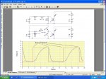
You can use the same method to drive the motor and the relay (but with 12V and 5V). See the excellent picture attached. The other picture shows the difference a driver can make to the signal. Blue = no driver, red = driver. (Note the timescale).

Hope this helps!

Andrew.

Ask if you have any other queries :)
 

Attachments

Last edited:

Brokenrecord

New Member
So from what I understand, pulsing a FET with low power means it takes longer to get above 4v, so in that time it generates more heat. But if you use a driver and increase the amperage, you minimize that time and thus create less heat? That seems to make a fair amount of sense.

What driver should I use then? The Darlington driver they sell with the picaxe seems fairly suitable but it only outputs .5A per pin. Should I wire 2 or 3 pins in parallel if I only need to control 2 or 3 groups of fans? Are the switching frequency and input amperage inversely proportional (so 100ms at 20mA would be equivalent to 2ms at 1A)?

And just to clarify, on post #6 you said "Use a MOSFET on the output between the picaxe and the realy - 20mA can't drive much." Did you mean between the picaxe and the relay controlling the 120Vac solenoid or between the picaxe and the fans? Thanks again for your help.

**EDIT: looking at your diagrams I understand what you meant by putting the mosfet between the relay and the picaxe. I was just stuck in the mindset of controlling current from the power side of things, not the ground side

**EDIT #2: one more thing, does the duty cycle always need to be 50% of the period?
 
Last edited:

Andrew Cowan

Senior Member
So from what I understand, pulsing a FET with low power means it takes longer to get above 4v, so in that time it generates more heat. But if you use a driver and increase the amperage, you minimize that time and thus create less heat? That seems to make a fair amount of sense. Correct. Capacitance is the measure of how long it takes to fill up and empty. Higher capacitance = longer. Higher current = faster.

What driver should I use then? The Darlington driver they sell with the picaxe seems fairly suitable but it only outputs .5A per pin. Should I wire 2 or 3 pins in parallel if I only need to control 2 or 3 groups of fans? The darlington driver chip would be slightly better than just connected to the picaxe, but that also has a small amount of capacitance, meaning it takes a short time for that to fully switch on. It all depends how fast you want to switch. If you want to go really fast (probably over 4KHz ish, (0.25ms on, 0.25ms off), then you need a FET driver. These are driver chips that have very low capacitance, so they switch on and off quickly. I use the MIC4427 - an 8 pin package with two drivers in it. You can get them as free samples from microchip.


Are the switching frequency and input amperage inversely proportional (so 100ms at 20mA would be equivalent to 2ms at 1A)? No - it is just that at lower frequencies the heat matters less. Imagine switching 10 and 1000 times per second. Say that it takes 1uS to switch on or off.

10 times per second generates heat 20 times per second (10 ons and 10 offs.)
20x1uS=20uS of heat per second.

1000 times per second generates heat 2000 times per second.
2000x1uS=2000uS of heat per second. Much harder to disipate, much more energy wasted.

(Note - the above is just a rough way of imagining it - it is not 100% correct). In other words, the same amount of energy is disipated every time it switches, so more switching per second = more heat given off.

And just to clarify, on post #6 you said "Use a MOSFET on the output between the picaxe and the relay - 20mA can't drive much." Did you mean between the picaxe and the relay controlling the 120Vac solenoid or between the picaxe and the fans? Thanks again for your help. The radioshack website says the coil resistance is 150 ohms. At 5V, this equates to 33mA. So some sort of driver is needed. You can use a FET, a transstor, or a darlington. No driver is needed for a FET in this case as you won't be turning it on and off hundreds of times per second. The fans will also need a driver - a FET is probably best for this.

Looking at your diagrams I understand what you meant by putting the mosfet between the relay and the picaxe. I was just stuck in the mindset of controlling current from the power side of things, not the ground side You can do either. However, these FETs need the voltage on the gate 9G) to be 4V high than the voltage on the source (S). See the attached diagram for why the FETs are used at the bottom (low side switch). The motor is the resistance, thus where the voltage changes. If you want a high side switch (relay at the top), you can either put a high voltage on the gate, or use a P channel FET. I was talking about N channel FETs.

One more thing, does the duty cycle always need to be 50% of the period? No. If you don't mind only being able to control the speed of two fans, then the two PWM ports of the 28x1 can be used along with the PWMOUT command. This sends a variable speed (pulsed) signal in the background, meaning the program can do other things without the program stopping. Have a look at the wizard in programming editor (PICAXE,Wizard,pwmout). You will see that you set the frequency, then the duty cycle.
0% duty = stopped
15% duty = power applied 15% of the time
100% duty = always on
etc

Andrew
 

Attachments

Last edited:

BCJKiwi

Senior Member
BR,
How does the system decide when to turn on/off the solenoids or, speed up/slow down the fans?

If there are 4 fans and you want to use PWM there will be issues with the available ports as all the fans will have the same speed. There is only 1 (or 2 depending on the PICAXE used) internal clocks that PWM can use.

Since this is a greenhouse application, one presumes there will be a large amount of thermal inertia so PWM Fan control may well be overkill. It may be easier to turn the fans on and off in response to a temperature input (all together or individually). As discussed above, a Logic level MOSFET gate on the PICAXE port, the fan 12V switched directly by the MOSFET.

The solenoids could be set up the same way with the mosfet driving the relay which drives the Solenoid.

The standard mosfet circuit is fine for this.

There is actually a Rev-Ed 18X product - CHI-035 which is a ready made board with 4 MOSFETS - may simplify the build significantly.

3 for solenoids, 1 for fans - if that's what you need.
 
Last edited:

westaust55

Moderator
120Vac solenoid control

Broken,

Since you are trying to control 120V AC solenoids, why not consider opto-coupled triacs. Traiacs which are intended for AC switching.

For an example have a look at:
http://www.dse.com.au/cgi-bin/dse.storefront/en/catalog/SUP1000073

Since you indicate 7 Watt rating that equates to around 60 mA current so even the example I have given is good for 150mA. And rated to 400V AC.
But, solenoid inrush current could be around 300+ mA.
 

Brokenrecord

New Member
How does the system decide when to turn on/off the solenoids or, speed up/slow down the fans?
Well what I would like to do would be to monitor two distinct areas of the greenhouse with digital temperature sensors and control up to 3 separate groups of 2 fans each. The solenoids would be controlled using a peroid/duty cycle type of schedule (tho I definitely will not be using the pwmout command for this :p)

Since this is a greenhouse application, one presumes there will be a large amount of thermal inertia so PWM Fan control may well be overkill. It may be easier to turn the fans on and off in response to a temperature input (all together or individually). As discussed above, a Logic level MOSFET gate on the PICAXE port, the fan 12V switched directly by the MOSFET.
That would be the easiest way to get things started but I'd like the fans to be as quiet as possible at all times so speed control would be a boon. And your right, having a MOSFET switch the 5V PSU for the solenoid on the high side (with a p-type FET I'm assuming?) would solve any problems with a lack of current, I will definitely do that.

There is actually a Rev-Ed 18X product - CHI-035 which is a ready made board with 4 MOSFETS - may simplify the build significantly.
Unfortunately the 18X just doesn't have enough inputs for what I want to do. I'd also like to connect a RTC, a 1024Kb EEPROM and a small LCD all using the i2c bus so that I can log data and display temperatures and warnings in real-time. Would each of those FET's be able to drive 2 .5A fans?

Broken,

Since you are trying to control 120V AC solenoids, why not consider opto-coupled triacs. Traiacs which are intended for AC switching.

For an example have a look at:
http://www.dse.com.au/cgi-bin/dse.storefront/en/catalog/SUP1000073

Since you indicate 7 Watt rating that equates to around 60 mA current so even the example I have given is good for 150mA. And rated to 400V AC.
But, solenoid inrush current could be around 300+ mA.
I know I've asked this before but do I need to optically isolate the 120v circuit? Or are you just suggesting that because it would be simpler? The relay from radio shack I showed earlier is rated at 1A, so wouldn't that easily be able to drive the solenoid?

And thank you guys so much for the help so far, I don't know what kind of 'magic smoke' I might be inhaling if I were just to dive into this all willy-nilly :D. By the way I'm currently pursuing a degree in computer science so coding all of this will be non-trivial.
 

westaust55

Moderator
The data for the radio shack relay you mention is:

- Maximum switching power of 10 (watt/VA)
- Maximum switching voltage of 60 VDC, 120VAC
- Maximum switching current of 0.5 A
- Maximum initial contact resistance of 150m ohms
-Type: OMR-112H
-Application: UL E822922
-Rated coil voltage: 5 VDC (at 20XXX°C)
-Operating voltage: 3.5 VDC (at 20XXX°C)
-Release voltage: 0.5 VDC (at 20XXX°C)
-Maximum applicable voltage: 8 VDC (at 20XXX°C)

I think you might find the 1A rating only applies at 5Vdc.

And a review comment from the Radio Shack site:
Can be driven by CMOS and TTL


But from the datasheet:
==================
Coil Data @ 20°C
Operate Data
Must Operate Voltage: 70% of nominal voltage or less.
Must Release Voltage: 10% of nominal voltage or more.
Operate Time: 1.0 ms max.
Release Time: 0.5 ms max.
Environmental Data
Temperature Range:
Operating: -30°C to +70°C
Vibration, Mechanical: 10 to 55 Hz., 1.5mm double amplitude
Operational: 10 to 55 Hz., 1.5mm double amplitude.
Shock, Mechanical: 1,000m/s2 (100G approximately).
Operational: 100m/s2 (10G approximately).
Initial Dielectric Strength Operating Humidity: 20 to 85% RH. (Non-condensing)
Between Open Contacts: 200VDC. (1 second).
Between Coil and Contacts: 3,000VDC. (1 second).
Surge Voltage Between Coil and Contacts: 3,000V (10 / 160μs).
Coil Data
Voltage: 6 to 24VDC.
Nominal Power: 100 mW to 280mW.
Coil Temperature Rise: 30°C max., at rated coil voltage.
Max. Coil Power: 160% of nominal.
Duty Cycle: Continuous.
Contact Ratings
Ratings:
100μA @ 5VDC, 100,000,000 operations.
1mA @ 5VDC, 50,000,000 operations.
5mA @ 5VDC, 50,000,000 operations.
5mA @ 12VDC, 50,000,000 operations.
10mA @ 12VDC, 50,000,000 operations.
100mA @ 12VDC, 10,000,000 operations.
100mA @ 24VDC, 7,000,000 operations.
200mA @ 24VDC, 7,000,000 operations.
400mA @ 24VDC, 5,000,000 operations.
Max. Switched Voltage: AC: 120V.
DC: 60V.
Max. Switched Current: 0.5A .
Max. Switched Power: 10VA, 10W.
OMR
Rated Coil Nominal Coil Must Operate Must Release
Voltage Current Resistance Voltage Voltage
(VDC) (mA) (ohms) ± 10% (VDC) (VDC)
5/6 24.0 250 3.50 0.50
9 12.9 700 6.30 0.90
12 11.4 1,050 8.40 1.20
24 11.5 2,080 16.80 2.40
Thats 24mA coil current at 5Vdc and the initial surge will be several times that.
Its all getting beyond the rating of dir3ect conenction to a PICAXE output.

Recomemndation:
some for of interface would be needed for that relay.

So its back to the Triac sugegstion
 

Brokenrecord

New Member
very true, but what about the circuit Andrew illustrated on post #8? I would need to put a diode on it to stop back emf but wouldn't the relay then draw all of its current from the 5V lead instead of through the picaxe? I just like the idea of using the radio shack relay because its conveniently located right next to me, though if they don't have anything else I need thats I can't buy at the picaxe store then it sort of defeats the purpose.

Does anybody know of a good place in wisconsin to buy electical supplies like FET drivers, MOSFETS, etc? So far radio shack has been googles only suggestion :eek:
 

papaof2

Senior Member
I buy most of my components online - MPJA, Jameco, All Electronics, Electronics GoldMine, Futurelec in Asia - because a even reasonably large metro area (Atlanta, GA) can have limited availability of some components. One distributor has been known for years as "the outhouse" because they are always out of whatever component you want...

John
 

westaust55

Moderator
very true, but what about the circuit Andrew illustrated on post #8? I would need to put a diode on it to stop back emf but wouldn't the relay then draw all of its current from the 5V lead instead of through the picaxe? I just like the idea of using the radio shack relay because its conveniently located right next to me, though if they don't have anything else I need thats I can't buy at the picaxe store then it sort of defeats the purpose.
Yes you can still go the way of the FET driving a relay powered from the +5V line with a flyback/freewheeling diode fitted across the relay coil.

In suggesting the Opto-coupled Triac is is a small device (6 pin DIP is usual format) and taking up less space than FET + Diode + relay.

At the end of the day, you ask for ideas/comments, forumites give many comments and solutions, but the final decision is always yours.
 
Last edited:

Brokenrecord

New Member
Thanks again for all your help guys. So I've taken what I could from your advice, downloaded some free circuit diagramming software (swCAD III I believe) and drew up my first actual schematic. I know its probably not organized well at all or in any way conventional, but it gives me a firm idea of what I need to do/buy. I've labeled all of the part #'s I plan to use so if any of you could give it a peruse and throw some pointers my way that would be great.


Also, I spliced an extension cord up and connected it to the solenoid last night. Everything seemed to work fine except that when it was plugged in it would give off a fairly audible hum. Is there anyway to suppress that? Maybe by limiting the current going to the solenoid? The distinction between limiting current and limiting voltage with a resistor (like andrew suggested in post #6) is very unclear to me.
 

Attachments

Last edited:

eclectic

Moderator
BR.

A few small points.

ADC0 – missing resistor to ground.

ADC1 and 2. Are they DS1820 or DS18 B 20 ? (Very different)
EditAdd:- READTEMP commands are used on "standard" inputs, not adc-inputs.

As a general “insurance” measure, add 10K resistors to ALL
unused inputs.
(ADC3 and In5,6,7)

I2C resistors to V+ (unless inside LCD)

Labels on download socket.

Capacitor(s) across Picaxe supply pins.

e.
 
Last edited:

lbenson

Senior Member
If DS18B20 parts, then 4K7 pullup on data lines needed. For ease of use, I think people here would recommend the DS18B20.

The circuit appears to go off the page to the right--can you provide the whole circuit--but maybe it's just the 120V lines?
 
Last edited:

Brokenrecord

New Member
eclectic, I'm working on a revision now. I do intend to use DS18B20, it was just a typo.

**EDIT: revision is below

"I2C resistors to V+ (unless inside LCD)" - What do you mean by that? looking at the datasheet I did seem to forget the 4k7 pull up resistors on the scl and sda lines, but I don't see any mention of a resistor on V+. And what type of capacitor do I need for the picaxe 5V line? Is it to regulate power? Because i'll be using a heavily regulated computer power supply

Also, the 120V lines just go directly to a power strip (unless I hear any reason to do otherwise, as I have no idea.). **EDIT: to be fair that's over generalizing things a bit. the 120V lines each make a circuit with a solenoid valve (rated at 7 watts) and a diode to prevent back emf.
 

Attachments

Last edited:

eclectic

Moderator
eclectic, I'm working on a revision now. I do intend to use DS18B20, it was just a typo.

"I2C resistors to V+ (unless inside LCD)" - What do you mean by that? looking at the datasheet I did seem to forget the 4k7 pull up resistors on the scl and sda lines, but I don't see any mention of a resistor on V+. And what type of capacitor do I need for the picaxe 5V line? Is it to regulate power? Because i'll be using a heavily regulated computer power supply

Also, the 120V lines just go directly to a power strip (unless I hear any reason to do otherwise, as I have no idea.)
Pullup = resistor connected to V+

"Inside LCD" = my sloppy language. The AXE033 has the pullup resistors on the board.

100nF, as close as possible to the Picaxe. MANY references on the Forum.
 

Brokenrecord

New Member
eclectic,
Is this what you meant by a 10k resistor on each unused input? I'll add the capacitor when I get home.

Also, I have two other questions.

1) How do I stop my 7 watt 120VAC solenoids from buzzing when plugged in?

2) the 120VAC relays I bought from circuit city are VERY small, is a small 26 AWG wire suitable for carrying that type of voltage? will I need a fuse, resistor or the like to limit the current so that I don't fry the wires?
 

Attachments

eclectic

Moderator
BR.
Just the first question.

Connect the unused inputs, via 10k resistors, to ground only.

At the moment, they seem to be connected to V+ and Gnd.
e

And, more questions.
post#7
"I apologize for being so new to electrical engineering"

No apologies required, but,

A. What IS your experience with high-voltage circuits?

B. What have you built, using Picaxe?
 
Last edited:

Andrew Cowan

Senior Member
You may be able to stop the buzzing by adding small capacitors across the 120V lines. 0.1uF, maybe?

I would go for 20AWG or lower wire for mains. It is current, not voltage that makes a heating effect, but at 120V, even with 60mA, I would say large wires to be safe. Less chance of the wires breaking.

As eclectic said, just put a 10K resistor between unused inputs and ground. Nothing else.

Andrew
 

Craftybytes

Senior Member
Just a thought - I've looked at your last updated circuit diagram -
retail greenhouse control system
1. Is this a 'stand-alone' unit connected closely to the relays (120VAC) & to the fans..?

2. OR - is this a control unit that is located several feet/yards (or metres) away from the actual power relay & 12V fan location(s)..?

3. How far from this control unit will the DS18B20 sensors be placed..?

If 2. above is the case - then I would recommend that you look at the possibility of using say 'individual' 08M based modules for localised control at each relay & fan & temp sensor location - AND - then link them back to this central 28X1 "control" module via say RS232 cabling..!!

Trying to drive long (several feet/yards/metres) cables connected to external relays (especially power relays) & fans from a central 'control' box is rife with potential "fault" conditions - WHEREAS - if each relay & fan point incorporates it's own 'localised' mini control module which communicates with a distant master - then one only need low voltage "comms" wiring betwwen each unit - shorter direct heavy duty power wiring is only then required at each power relay point..

Worth considering..

crafty.
.
 

Brokenrecord

New Member
First, eclectics questions:

"A. What IS your experience with high-voltage circuits?"
Other than installing new outlets I've had no prior hands-on experience with high-voltage circuits. However I do work at a company that works directly with high-voltage circuits so I've been trained and "certified" to come in contact with them. Whether that will help me or not remains to be seen but they did give me a nice pair of gloves rated to withstand a 1000v arc

"B. What have you built, using Picaxe?"
Nothing as of yet. I was going to buy the 08M start pack in edition to everything else so I can work my way up to the 28X1. I was thinking somewhere along the lines of blinking and scheduled blinking leds, controlling the fans via mosfet, turning a 120v light bulb on and off, etc. The picaxe seems like a fairly simple and intuitive little microcontroller that I saw as a fun way to bring my code to life, so I'm hoping that as long as I follow all the rules closely I won't be too bad off.

Andrew:
I'll try the capacitor idea, would a band-stop filter work as well?

Crafty:
It will be more along the lines of option 1. The power supply and fan control will be together and wires no more than 2 meters long will run to each fan and to a seperate metal case where the solenoids will be controlled. Is that a likely scenario for causing potential fault conditions? I was also thinking of putting fuses between the main lines and their circuitry as well as between the picaxe control board and the solenoid control board. Good idea or is that just a little overkill?

P.S.
Is it looking better now?
Thanks for the help
 

Attachments

wapo54001

Senior Member
12vdc fans do not handle pwm style speed regulation very well at all -- its hard on them, and they are noisy when driven that way. It is far better to regulate the input voltage to control speed.

One way to do that with three discrete speeds is to use a 7812 and a 7805 (or use a computer power supply) to make three voltages available -- 12v, 5v, and 7v (12v-5v=7v). You can use relays to switch between those if desired.

A better way is to control fan speed is to use the 08M picaxe as a voltage regulator to control up to about 1.5amps as described in the recent thread about using the picaxe as a voltage regulator. You can use a temperature-measuring device connected to the input readADC to control the output voltage which will change fan speed, and there is plenty of room in an 08M to put in special code like limiting max and min voltages, supplying a second or two of max voltage to start the fan before reducing speed by lowering voltage, etc. It can be a compact circuit -- I have built a 2x2 inch circuit card which does all of that plus includes a separate 08M-controlled power mosfet that acts as an available on/off switch.

All you need is an 08M (fed regulated +5 by an lm78L05), a few resistors and capacitors, a mosfet, and an LM317. The software and schematic are already published in a recent thread but I've included both below.

You can have a completely separate power supply at each location, or you can string 12vac wire from a central power point to wherever you want the fans to function, and convert it to DC and filter it at each bank of fans.

Use the attached schematic, replacing P1 with a temperature measuring device, connect the fans to the LM317 output. use this code in an 08M to drive the fans as you would wish. You can either use a straight line formula to convert an input voltage range to a completely different output voltage range, or you can specify multiple input ranges to target specific output values (so that a temperature range of say, 5 degrees, will drive the fan to a specific voltage value).

Here is my version of the code which you can modify to work with your requirements:


Code:
#REM
Adjustable Voltage Regulator
NO JITTER on output
Picaxe 08M
Leg (Pin) Use
 1    -   +5
 2    -   SerIn (to GND)
 3   (4)  ReadADC10 (Input)
 4   
 5   (2)  Output
 6   (1)  readADC10 (Output)
 7   
 8    -   GND

W0 = Input readADC10 & averaged input
W1 = 
W2 = Output readADC10 
W3 = Difference Value between Averaged Input & Output
W4 = saved input value
W5 = saved input value
W6 = saved input value

#endrem

'Program

'identify chip to compiler
#picaxe 08M
'set clock to 8MHz
setfreq m8
'set output to lowest voltage during startup
low 2

main:

'read input
readadc10 4,w0  
'retain last three read values
w6 = w5
w5 = w4
'multiply by 20 to achieve better resolution
w4 = w0 * 20
'calculate the average input value  
w0 = w4 + w5 + w6 / 60 


'adjust:
readadc10 1,W2  			'read current output voltage
if W2 = w0 then			'compare to input voltage
	input 2    				'if identical, goto main & restart cycle
	goto  main     
EndIf

'increase:				
if w0 > W2 then 			'if input is higher than output
	W3 = w0 - W2			'calculate difference
	If W3 < 2 then main 	'if difference is less than 2, go to main
	low 2    				'else, reduce gate drive to increase resistance & voltage output
	goto main
EndIf

'decrease:
W3 = W2 - w0				'if output is greater than input
If W3 < 2 then main 		'if less than 2 difference, goto main
high 2    					'otherwise, increase gate drive, lower resistance, lower voltage
goto main
'end of program
 

Craftybytes

Senior Member
In your latest circuit diagram -

1. you have the +v pin of the 28X1 connected to +5V thru a capacitor - doesn't work that way - you need to connect the +v pin direct to the +5V line - then connect say a 100nf capacitor from almost next to the +v pin down to the 0V line..

2. recommend use 12V relays (not 5V ones) and connect your fans AND the relays to the +12V line ONLY - then connect all the other digital circuitry to the +5V line - helps to minimise interference from switching and 'load' spikes AND separates the supply lines from "output" devices & "control" devices..

3. Fuses probably would not hurt as you suggest..

HTH.

crafty.
.
 

Brokenrecord

New Member
Hey wapo,
I've read through Haxbys thread (that took me a while haha) and I actually think that technique can really work for me. My master plan was to record the temp data (using the DS18B20 on pin 4) and have it stored in eeprom memory, for download and later analysis in a PC.

To do that I was thinking I would set pin 3 high using a larger "master" picaxe, the 08m would then recognize that flag when preforming the main method and quickly sertxd the temp data to the master before returning to regulating the fan voltage. Would this method cause less disturbance in the voltage regulation than using an interrupt on pin 3?

While reading through the thread I noticed that it was mentioned that the MOSFET used isn't necessarily important. Does this mean an IRF510 would work?

Also, I noticed that the LM317 outputs 3v lower than the supply voltage. In my case that would be only 9v. Is there a way I could switch it to 12v when that kind of voltage is really needed (say by bypassing the regulation circuit with with a spdt relay, if thats possible?)?
 

wapo54001

Senior Member
Hey wapo,
I've read through Haxbys thread (that took me a while haha) and I actually think that technique can really work for me. My master plan was to record the temp data (using the DS18B20 on pin 4) and have it stored in eeprom memory, for download and later analysis in a PC.

To do that I was thinking I would set pin 3 high using a larger "master" picaxe, the 08m would then recognize that flag when preforming the main method and quickly sertxd the temp data to the master before returning to regulating the fan voltage. Would this method cause less disturbance in the voltage regulation than using an interrupt on pin 3?

While reading through the thread I noticed that it was mentioned that the MOSFET used isn't necessarily important. Does this mean an IRF510 would work?

Also, I noticed that the LM317 outputs 3v lower than the supply voltage. In my case that would be only 9v. Is there a way I could switch it to 12v when that kind of voltage is really needed (say by bypassing the regulation circuit with with a spdt relay, if thats possible?)?
Brokenrecord,

1. I can't speak to the interrupt vs pin high method of branching the code -- suggest you try both and see which is better.

2. Re the mosfet -- I used a 2n7000 which worked very well. If you go back and read the threads I mention in my first post, you'll find that when testing the circuit, wilf_nv used the 2n7000 and one other (power) mosfet, and both worked. Also, BCJKiwi has tried several mosfets that seemed to work OK, but some better than others. I recommend the 2n7000 -- dirt cheap and works very well. Suggest you compare the IRF510 data sheet with that of the 2n7000 to see if the 510 will work. If you use the mosfet as I've described, the current through it is absolutely trivial, and you don't need a power device.

3. I seem to remember that the 3-volt issue was mentioned in the haxby thread -- I think BCJKiwi posted that remark, but I'm not sure. If you can find the quote, why don't you re-post it here, or ask BCJKiwi to elaborate (if in fact he is the one who mentioned the problem). Looking at the LM317 specs, I see that a Vin - Vout differential must be at least 3 volts for proper regulation, but if the voltage is already regulated at 12V maybe that won't matter?

4. Your bypass relay idea might work, but don't you have a raw voltage higher than 12vdc available to feed the lm317? Where are you getting your regulated 12vdc? could you run unregulated higher voltage to the lm317 and allow it to regulate from 1.25v to 12 or more volts for the fan? That would be my choice.
 

BCJKiwi

Senior Member
I presume the adjustable regulator is to provide variable voltage & thereby speed for the fans instead of PWM.

The 3V is out of the National Datasheet.
While testing it seemed to work with Vin only 1V more than Vout. However I would expect regulation and load capability to be compromised. Regulation won't be critical in this app so give it a try. The effect would presumably be that full voltage won't be achieved but watch for heating as well.

The LM317T is good for 1.5A with proper heatsinks. If the fans are drawing significantly less current then you would probably get close to 12V which may well be enough.

Where is the 12V coming from? If there is a PSU to be purchased/built then could it be 15V instead?
 

Brokenrecord

New Member
Well it sounds to me like I'll have to experiment a little bit to see if everything works out ok. The 12v fan supply and 5v picaxe supply are all coming from a used 150 watt computer power supply that I picked up for 3$. I could try to hunt down a 15v wall wart for cheap and use it for specific fans that would need full power.. I'll look into it. I don't know how long it takes to airmail my order from the UK to the US but it got dispatched yesterday, so hopefully it will be here soon. I'll post on here when I have a working circuit or if I have more trouble!

I do have one more question, The power supply is rated for 150 watts but that doesnt mean it draws that much power all the time does it?
 
Last edited:
Top