08M2 weak output question

Greg S

New Member
I have a small battery linking project I am working on which is to keep an auxillary battery charged without overcharging it. I am using a picaxe 08M2 to sample the voltage of both batteries and tun on a mosfet transistor to link the batteries. I am driving the gate of the Mosfet (MTP50P03HDLG) with a 2N2222 to ground through a 1K resistor working against a 100K pullup resistor. The 2N2222 is driven from pin c1 through a 100K resistor. The problem I have is I am only getting about 1.5 volts out of pin c1. Now the perplexing part is if I change the program to make the output normally high and switched low I get 4.97 volts out of c1.

Any ideas

Greg
 

Attachments

rq3

Senior Member
I have a small battery linking project I am working on which is to keep an auxillary battery charged without overcharging it. I am using a picaxe 08M2 to sample the voltage of both batteries and tun on a mosfet transistor to link the batteries. I am driving the gate of the Mosfet (MTP50P03HDLG) with a 2N2222 to ground through a 1K resistor working against a 100K pullup resistor. The 2N2222 is driven from pin c1 through a 100K resistor. The problem I have is I am only getting about 1.5 volts out of pin c1. Now the perplexing part is if I change the program to make the output normally high and switched low I get 4.97 volts out of c1.

Any ideasour wiring very carefully

Greg
Without a schematic I can only guess. But I think your 2N2222 does not have enough base drive. Try 1K instead of 100K from C.1 to base. And check your wiring very carefully! Something is fundamentally not right, but without a schematic...?

Merry Christmas!
Rip
 

Greg S

New Member
schematic for battery linking controller

I don't know what I was thinking , it did not occur to me to add the scematic so here it is.

Thanks Greg
 

Attachments

premelec

Senior Member
Not getting enough voltage out of 08 pin C.1 indicates some wiring problem - check C.1 with loads disconnected - 100K is much higher than appropriate as rq3 says but that shouldn't load C.1... Perhaps post a picture of your wiring as well...
 

Greg S

New Member
Not getting enough voltage out of 08 pin C.1 indicates some wiring problem - check C.1 with loads disconnected - 100K is much higher than appropriate as rq3 says but that shouldn't load C.1... Perhaps post a picture of your wiring as well...
with the 100k out of circuit and c1 not connected I get 4.94 vdc. substituting a 1k in place of the 100k drops the voltage back to 1.4-1.5 vdc. plus I have tried two different 08m2's with the same result. what bothers me is that if I change the program to make c1 normally high i get normal voltage but with c1 normally low i get reduced voltage when it goes high.

Greg
 

premelec

Senior Member
Sounds like a floating V- or some such - please post picture of your setup. 100K shouldn't load it so it indicates the C.1 source is very high impedance - but there's no way to know why without showing where your meter is connected and how the hardware is setup. With unit off test continuity of V- to actual PICAXE pin [and check which pin...] as well as V+ continuity to the chip. Maybe bad joint somewhere [continuity test with ohmeter...] - From what you say about C.1 that may indicate a program error... back off to very simple on - off instructions and make sure they work and if you can't sort it out post your program... Try the TOGGLE instruction which simply reverses pin state... if that works you'll have a further clue. " i get reduced voltage when it goes high." in short it DOESN'T go high...
 

darb1972

Senior Member
Hello Greg

I have started looking at your schematic. I am out of "the office" so I am looking at this on my tablet. Given my limited resources I will do my best to assist. R8 on the base of Q4 is NOT your issue, but the value could be a little lower. I will explain. R11 and R12 form a voltage divider from VB when Q4 is turned on. Assuming a VB voltage of 13.8V (automotive working voltage) the voltage across R11 is 1.2545V. The resultant collector current Ic is 0.0012545455 Amps. Assuming a hFE (DC gain) of 75 (a reasonable average for this transistor) and allowing a saturation factor of 3, the nominal current at the base of Q4 is 0.0000501818 Amps. This results in value of 85,688 Ohms. Using preferred values this might result in using a 100k resistor or in my opinion, use an 82k resistor ( but a 100k will do). 1k Ohm is too low. It probably wouldn't do any harm (like punch a hole in the base PN junction and send it short), but it is a waste of system power (which matters in some cases).

Now back to your issue. Have you tried disconnecting the programming port? Maybe there is some sort of low impedance between the PICAXE pin and the programming port? Something must be pulling the voltage down. As suggested, use a multimeter to find the issue. Disconnect the power. Put the multimeter into measuring resistance. Put the negative probe to ground. Put the positive probe on the problem pin. I would suspect that you should measure several 10s of kOhms in normal circumstances. From what you have reported, I suspect you might read very low ohms. Use this to troubleshoot the issue further.

Let us know how you get on.
 

Greg S

New Member
Ok circuit un powered and R8 out of circuit i measure 193K ohms from ground to output pin C1 but interestingly I measured Ground to C0 and I get 9.95 Mega ohm. I can not see any thing that would pull the pin down. All measurements look ok. I don't see how the programming port would affect pin C1 because it is not connected to it, also pin C0 which is the serial out pin during programming operates fine when working as the sampling output. and if I reverse the operation of output C1in the program I get 4.94 volts high and 0.0 volts low as expected. When programmed correctly I get 1.4-1.5 Volts high and 0.0 volts low
 
Last edited:

darb1972

Senior Member
Hello Greg

Sorry, I misread the schematic and thought C1 went to the programming port. My mistake.

The measurements between Ground and C.0 and C.1 certainly don't seem out of the ordinary, however the 9.95M Ohms on C.0 seems on the high side for a Pin with circuitry hanging off it. Regardless, this shouldn't be related to the problem at hand. One other thing you can try is to remove Q4 and put R8 from the pin to ground. Put your multimeter across this resistor and measure the voltage. This will "load" the pin but exclude all other circuitry. If the problem persists, you could substitute the same resistor in the same test and change the value to, say, 10k Ohms. If this works then maybe it is a case of the 100k Ohms resistor not allowing to PICAXE to source/sink sufficient current to operate correctly (although I thought 100k Ohms isn't that high). Mind you, at 4.3V across R8 when the pin should be high (allowing for the Base/Emitter 0.7V drop on Q4) the current through this part of the circuit is only about 43uA. That's a small current. Try that experiment and see what happens.

If none of that works then I am thinking that the issue must be software related as opposed to hardware, even though the problem seems perplexing.

I am trying to understand how the program works. Do you have a copy of it in BASIC as opposed to a Flowchart? If I get the PE to convert it from a Flowchart to BASIC the program is a bit messed up. Can you please post a copy of it in BASIC?

Thanks.
 

AllyCat

Senior Member
Hi Greg,

Has your circuit ever been connected to any automobile electrics yet (or are you still testing "on the bench")? If so, the PICaxe (or almost any of the components) might have been damaged by a high voltage spike, which is a hazard of that environment. IMHO your circuit needs more filtering / decoupling components to be "safe" (i.e. reliable). Also, I have other "concerns" about the design, but most fundamentally:

I have a small battery linking project I am working on which is to keep an auxillary battery charged without overcharging it.
Are you sure the design is correct? The P-channel FET appears to be configured to control current flowing from the AB to the VB, and R12 appears able to turn the FET on if the voltage difference is greater than the threshold voltage, regardless of the drive from the PICaxe.

Also, your diagram doesn't show the FET's internal "commutating" diode which will conduct whenever VB > AB + 0.5 volt.

Cheers, Alan.
 

Greg S

New Member
Hi Allan thanks for catching that. The drawing of Q5 was in the scematic drawing program I used and does not match the MTP50P03hdlg correctly and I did swap VB and AB on the scematic although the actual cirquit is wired correctly with source connected to VB and drain to AB

Thanks Greg
 

Greg S

New Member
Let me try and explain it from memory. when the Ignition comes on the 08M2 wakes up then waits 30 seconds after which output C0 goes high turning on the votage sampling circuit. next the program reads both batteries voltage into the variables A1 and B4 (I could be wrong on the variable logos). Next it should check to see if VB is greater than 13.5 VDC. Next it checks to see if VB is greater than AB and if AB is less than 14.1 VDC If all is well the output C1 goes high to enable the SCR. When AB reaches 14.1 VDC output C1 goes low turning off the SCR. then the program loops back to the sampling part of the program and repeats.

I hope this clears it up a bit
Greg
 

Greg S

New Member
Allan I forgot to mention that I have had the circuit briefly connected to the vehicle and it did not work so it came off and back to the bench. I will sat the I have changed to anothe 08M2 chip after it returning to the bench and the results were exactly the same. I will add some more filtering to the circuit prior to reinstalling it.

Thanks Greg
 

AllyCat

Senior Member
Hi Greg,

I think I saw an "A4" in the flowchart which probably should be (pin) C.4, but otherwise the flowchart looks plausible (we can't mind-read what is trying to be achieved).

9 Mohms is very much the resistance of a "wet finger" (or even a fairly dry one) so might be a "misleading" measurement. Even the transistors could have been damaged by a 100 volt spike from the auto electrics (but probably not in this case). However, I'd definitely add electrolytic capacitors (at least) each side of the 7805.

I doubt if it can be done directly in Logicator, but the "trick" I would use is to drive the "reference voltages switch" transistor base directly from pin C.3 ("input only") rather than from C.0 (Serial/Programming output). No series resistor needed (I'd connect the 100k across base-emitter to ensure it's normally off) and you can enable the transistor with a (Basic software) "PULLUP 8" (the 8 specifies pin C.3) and disable it with "PULLUP 0".

Cheers, Alan.
 

Greg S

New Member
Alan that is an interesting idea about using an input as an output I never thought about that. The reason I used C0 as an output is becauce I did not have enough output pins and C3 is listed as not having an AD converter so I did not use it as an input to free up another pin for an output. Though this part of the circuit is working fine as is I still need to get to the bottom of why C1 does not act right and I am still not convinced that it is not some quirk in the way the logicator software converts the flowchart to basic during programming.

Thanks Greg
 

AllyCat

Senior Member
Hi Greg,

Certainly the c.0 and c.1 pins are "unusual" in that the base chip hardware uses them for a DAC output and Reference Voltage input respectively. As such, it's possible that "wrong" software (or perhaps a chip "zapped" by a high voltage spike) could put around 100 kohms internally onto the pin (the reference chain is 32 x 5k resistors in series). But to be honest, I'd first be looking for a more obvious external cause. However, I have myself found a few "bugs" in the firmware (e.g. in readinternaltemp) which I was surrprised hadn't been spotted sooner.

Yes c.3 is fundamentally only a digital input. The weak pullup has quite limited (current) capability at a nominal 30 kohms (maybe higher) and needs a "non-standard" output command, but is the solution that I would use in such an application.

Cheers, Alan.
 

Greg S

New Member
Battery linking controller basic program

Here is the flow chart program converted to basic by the logicator program
Another interesting bit of information. I replaced R8 with a 100K resistor and when C1 goes high I get 4.94 volts which is the same as V+, substituting a 10K resistor in place of R8 the C1 voltage drops to 4.92 Volts. hooking the 10K back to Q4 the voltage drops back to 1.5 or so. I replaced Q4 just to be sure it was not bad. I do not understand how Q4 can load C1 more that going to ground through the same resistor. going back into the program I swapped the SCR on and off commands to make the C1 output high until commanded low and I get 4.93 volts on C1 and 0.53 volts on the base of Q4 for a voltage across R8 of 4.4 volts. As a reference with the program as intended I get 1.5 volts on C1 and 0.18 volts on the base of Q4 for a voltage across R8 of 1.32 volts. I have beet all over the circuit with the ohm meter and I can not find any bad solder joints.

Greg
 

Attachments

AllyCat

Senior Member
Hi Greg,

The "Basic" attachment still appears to be a Logicator flow chart (empty) with the .plf file extension. :confused:

I'm still puzzled by the "readac A4 , varA" cell in the first chart. However, from your latest description, I suspect that one of the variables (varA ?) is changing for each pass around the main loop so that the result is C.1 high for only one pass in every three. Thus it could be generating a "PWM" signal that the multimeter averages to 1/3 of the "true" voltages.

Cheers, Alan.
 

darb1972

Senior Member
Hi Greg

I am glad to see Alan has managed to help you make progress. Here is a silly question but is easily overlooked. Is the ground for the PICAXE circuit tied to the Automotive ground? If not, it should be, and might explain some of the weird issues.

I am going through your program at the moment. There might be some room for simplification. In the meantime, can you remove Q5 from circuit and try the attached test circuit (essentially it is just Q5 removed with no other changes to your circuit). Also try the attached test program (with your current 08M2). With a DMM attached across the Collector/Emitter of Q1, when the output is high on C.1 the DMM should read close to 0V (the transistor is on). When the output on C.1 is low, the DMM should read close to VB (maybe 13.5 to 13.8V)(the transistor is off). The attached program should make the voltage across the DMM 0V for 10 seconds, then 13.8V for 10 seconds in a continuous loop. Does this work???

If this works then it is either an issue with Q5 (as Alan suggests, don't forget the Source to Drain diode) OR it is something with the program (I am looking at that and will post again shortly).

I am out of the office/workshop at the moment so I can't test any of this.
 

Attachments

darb1972

Senior Member
Hello Greg

I am glad you brought this project to the forum. I have an interest in this sort of project and was on the verge of adding a new and improved dual battery controller to my service van. While on the subject of the controller itself, do you think the FET has adequate current capability? It is only 50 amps and if your Aux battery gets low in voltage the initial current upon connection to the vehicle battery might be very high (although I am not sure exactly how high). Someone who is more proficient in battery theory might be able to elaborate on this parameter.

Anyway, onto the software...................

Please see below and attached. I took the liberty of simplifying your original code. I also included a number of comments and symbols to assist in understanding the program flow. I gather that the PE created your .bas file from the flowchart. It wasn't real easy to decipher in it's raw form.

The code below follows your original code identically so if it doesn't do as expected it is much easier to edit when compared to the converted code. Hopefully this will assist in spotting any problems or making improvements.

Regards,

Brad


Code:
;;;;;;;;;;;;;;;;;;;;;;;;;;;;;;;;;;;
;     Dual Battery Controller     ;
;;;;;;;;;;;;;;;;;;;;;;;;;;;;;;;;;;;


;Symbols 

symbol Veh_Volt = b0
symbol Aux_Volt = b1
symbol Veh_Batt = c.4
symbol Aux_Batt = c.2
symbol Sample_Cir = c.0
symbol Batt_Control = c.1


let dirsC = %00000111


main:
		pause 30000				'Pause for 30 seconds
		high Sample_Cir			'Turn on battery voltage sample circuits
		
		
Sample_Batt:

	Do
		readadc Veh_Batt,Veh_Volt	'Read and store the vehicle battery voltage
		readadc Aux_Batt,Aux_Volt	'Read and store the aux battery voltage
		
		if Veh_Volt >= Aux_Volt and Veh_Volt > 185 and Aux_Volt > 174 then low Batt_Control
			else high Batt_Control
			
		end if
			
	Loop
 

Attachments

Greg S

New Member
Test results with your test program loaded and veh battery voltage at 13.94. I get 13.94 across Q4 with Q5 disconnected. there is 4.93 volts on C1 when high 0.0 when low and 0.53 volts on the base of Q4. so this test seems a success.

I then programmed the circuit with your simplified basic program and it does run with C1 output at 4.93v. A couple of issues the criteria of waiting until VB has recovered to 13.5 volts has been lost as Q4 and Q5 come on as soon as the 30 second pause is over so I think a little tweaking of the program is in order. I suspect that the issue all along may have been how the logicator program converted the flowchart to basic. There are still some things I don't understand about the way it was behaving at times but I am very pleased to have made progress and thank you all for your help.

Greg
 

Greg S

New Member
One other issue is when C1 goes low it only drops to 1.9-2.1 volts so I think there needs to be a C1low command in there when it should be off
 

darb1972

Senior Member
One other issue is when C1 goes low it only drops to 1.9-2.1 volts so I think there needs to be a C1low command in there when it should be off
Hi Greg

Great to hear you are making progress. I would have expected c.1 to go lower than that. The program already includes a command to take c.1 low IF all the conditions are met, otherwise it goes/stays high. I am not sure why, but you have what seems like a residual voltage on the pin. It might be damaged pin? Mind you, the load on pin is small when compared to many typical loads.

You could try putting a 10k or a 4.7k resistor from c.1 to ground to see that pulls the "low" low. It doesn't make sense that when the command sends out a low to pin c.1 it is still sitting at around 2 volts. Didn't you mention that on the test circuit and program c.1 went to 0 volts on a low command?

Try the resistor and let me know how that goes.
 
Last edited:

Greg S

New Member
During the test program pin C1 did in fact go to 0.0volts but while running the program you sent it did not go to 0v. I did try a 100k resistor and it pulled C1 down to about 1volt. I will try some other values when I get home after work.
I believe someone was questioning why I an only using a 50 amp MOSFET. The auxiliary battery will be running amateur radio gear and the two batteries are mounted at opposite ends of an SUV and connected with 8 guage cable.
Thanks Greg
 

darb1972

Senior Member
Hello Greg

I had another thought about the voltage not appearing to go "low" all the way to zero volts. It might be that the circuit is "hunting" rather than sitting on one setting. Depending on your upper and lower threshold settings, the circuit might be turning on and off in a very quick fashion. This would give the impression that the low (and maybe the high) is sitting at an average voltage (somewhere around midway depending on the mark to space ratio). You would only successfully see the switching on a CRO. It's worth consideration.

I was the one that mentioned about the battery and FET current. There are plenty of factors to consider when it comes to battery design. I am not experienced enough to guide you on this part on the project.
 
Last edited:

Goeytex

Senior Member
With a substantial difference in voltage between the Vehicle battery and the aux battery there can/will be a very high current flow through the FET, with the current only being limited by the internal resistance of the batteries and the on resistance of the FET. This current needs to be limited in one way or another. A direct connection (as in the schematic) is a recipe for disaster.
 

AllyCat

Senior Member
Hi,

the circuit might be turning on and off in a very quick fashion. This would give the impression that the low (and maybe the high) is sitting at an average voltage ..... You would only successfully see the switching on a CRO. .
Yes, that's much what I suggested in #18. It might be possible to verify simply by adding a PAUSE 1000 near the top of the loop (before it branches), but it would depend on what is causing the different paths to be followed (e.g. a software "bug" or hardware "noise").

the two batteries are mounted at opposite ends of an SUV and connected with 8 guage cable.
An auto battery is designed to deliver at least 500 Amps to crank the starter motor, so not much current limitation there. The resistance of 8 AWG wire is about 0.7 ohms/1000 feet, so 0.01 ohm for 15 feet. Therefore, perhaps 100 Amps for 1 volt drop (with a chassis earth return), or half that with "twisted pair" cabling.

However, as I ponted out in #10, even with the PICaxe generating an "Off" signal, the bias resistor R12 will turn the FET On if Vds is above about 2 volts. At 50 Amps, if Vds = Vgs = 3 volts, then the FET will dissipate around 150 watts, so I hope at least it's bolted to the chassis as a heat sink! If the "analogue" design isn't "safe", then there's nothing that even the best PICaxe software can do to save it. ;)

Cheers, Alan.
 

darb1972

Senior Member
Hi Greg

Further to what Goey and Alan have said, and what I was tending to suggest, the current flow is likely to be (initially) very high under normal circumstances. It might be worth a rethink of the design and seriously consider using a (or several in parallel) solid state relays (dc/dc). This would reduce the switching complexity and avoid excessive current through the existing FET design. Mind you, even with high current ssr components, you will still need to heat sink them due to a small voltage drop at high currents. Only when the batteries get close to equalization will the current drop to low levels.

If you are still going to sample both voltages you would still need to add anti-hunting into the software (as per Alan's suggestions). If you don't, the system will be switching like crazy and this might shorten the life of several components and I am not sure what high frequency/high current switching will do to the batteries.
 

Hansb56

New Member
Hallo,

I made some year ago a simulair product for my son.
During the holidays he puts in a (big) auxilary accu in his van. To prevent to empty the normal vehicle accu to fast by using lighning, a little fridge etc.
With one relais I shut down the output of the aux-accu (Acc) when U-acc becomes to low to prevent to damage the aux accu.
With the other relais I can couple both Accu's. This happens when U-Accu of the car (vtg) is above about 13,8V. That's when the engine is running.
I separate both accu's when they come below about 12,5V. So the vehicle accu has enough power to start the engine next morning.
For details see the program and the schematic.
It was one of my fist projects, so excuse if some of the programming can be better.
The comments are in dutch :), but I'll explain if needed.

Greetings

Hans

Code:
Code:
'accuscheider def 1.5 25 mei 2013
'programma scheidingsrelais voor twee accu''s nu 229 van 256 05-02-2013
'gebruik 20M
'configuratie:
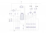
'inputs: 	pin 9=input1=adc1=accu1=vtg
'		pin 8=input2=adc2=accu2=acc
'		pin 7=input3=adc3=Uuit
'		pin 5=input5=druktoets
'		pin 18=output0= LedH = b.0 = gr
''outputs	pin 17=output1= R1   = b.1
'		pin 16=putput2= LedM = b.2 = gr
'		pin 15=output3= R2   = b.3
'		pin 14=output4= LedL = b.4 = ge
'		pin 13=output5= Red  = b.5 = ro
'		pin 12=output6= LedR2= b.6 = gr
'		pin 11=output7= LedR1= b.7 = ge
'
'Variabelen toewijzing:
'b0=teller
'b1=ingelezen outputs
'b2=Avtg
'b3=Aacc
'b4=Uuit
'b5, b6, b7 tijdelijke variabelen bij 'lees'
'b8= Leds3 = 13.8V
'b9= Leds2 = 12,2V
'b10= Leds1= 11,6V
'b11=hoog =13,4
'b12=mid  =12,8
'b13=laag =11,4


'Overzicht van spanningsniveau's en acties
'tehoog = 16V   = 140 ==> Aacc wordt afgeschakeld (open R1)
'leds3  = 13,8V = 124 ==> bij 13,8V gaat de derde (groene) led aan
'hoog   = 13,4V = 120 ==> bij Avtg=hoog gaat R1 aan (koppelen twee accu's)
'mid    = 12,8V = 114 ==> bij Avtg<mid gaat R1 uit (loskoppelen twee accu's) 
'bij 	  > leds2 gaat R2 aan
'leds2  = 12,2V = 110 ==> bij leds2 gaat de derde groene led uit, blijven 1 groene en 1 gele over
'leds1  = 11,6V = 104 ==> bij leds1 brand alleen de gele led nog, < leds1 nog alleen de rode 
'laag   = 11,4V = 102 ==> bij laag schakelt R2 de verbruikers af
'telaag = 10V   =  92 ==> bij te laag (accu defect of geen 2e accu) 

'************************************************************************************************************


Init:
	symbol toets=pinc.5
	symbol ledR1=b.7
	symbol ledR2=b.6
	symbol R1=b.1
	symbol R2=b.3
	symbol red=b.5	
	symbol tel=b0
	symbol Avtg=b2	'c.1
	symbol Aacc=b3	'c.2
	symbol Uuit=b4	'c.3
	symbol leds3=b8
	symbol leds2=b9
	symbol leds1=b10
	symbol hoog=b11
	symbol mid=b12
	symbol laag=b13


	hoog=120
	mid=114
	laag=102
	leds3=124
	leds2=110
	leds1=104
	'tehoog=140
	'telaag=92
	
	let pins = %11110101 'high ledr1,ledr2, red + 3 spanningsleds
	pause 1500
	let pins=0
	goto main

Main:
	gosub lees
	gosub disp
	gosub schakel
	goto main
	
Lees:	'lees en deel door twee, twee keer, geeft waarde in ca 4 sec
	let Avtg=0
	let Aacc=0
	let Uuit=0
	let tel=1
	for tel= 1 to 2
		readadc c.1,b5 'Avtg	'b2
		b5=b5/2
		Avtg=Avtg+b5
	
		readadc c.2,b6 'Aacc 	'b3
		b6=b6/2
		Aacc=Aacc+b6
	
		readadc c.3,b7 'Uacc 	'b4
		b7=b7/2
		Uuit=Uuit+b7
		pause 1000
	next tel

	'check op aanwezigheid 2e accu / te lege accu
	If Aacc < 92 then let pins=%00110000 let Avtg=0 endif 'rood, geel
	'check op te hoge accuspanning
	If Avtg >= 140 then let pins=%00110001 let Avtg=0 Aacc=0 endif 'rood, geel groen2
	return
	
Schakel:
	if Aacc <= laag then low R2 low ledr2 endif	'Accu2 < 11,4V: uit
	if Aacc > leds2 then high R2 high ledr2 endif	'Accu2 > 12,2V: aan
	If Avtg >= hoog then high R1 high ledr1 gosub slope endif 'accu1 > 13,4V: aan
	if Avtg < mid then low R1 low ledr1 endif	'accu1 < 12,8V: uit
		
	return
	
slope:
	pause 2000		'pause 2 sec
	readadc c.1,b5	'lees in b5 = startwaarde
	let tel=0		'max gedurende 5 min in deze subroutine
	do while b5<= mid and tel<150 and b5> laag 'blijf laden zolang b6> start (b5)
		pause 1000
		let aacc=b5
		'debug
		gosub disp
		pause 1000
		tel=tel+1
		readadc c.1,b5	'lees in b5
		
	loop
	return

Disp:
	readoutputs b1
	b1=b1&%11001010			'zet U-leds uit, laat rest
	if 	Aacc >= leds3 then	'>13,8V groen2
		pins=%00000101 or b1
	endif
	if Aacc>=leds2 and Aacc < leds3 then	'>=12,2V en < 13,8V groen1
		pins=%00000100 or b1 
	endif
	if Aacc>=leds1 and Aacc < leds2 then 	'>=11,6V en < 12,2V geel
		pins=%00010000 or b1
	endif 
	if Aacc>=92 and  Aacc < leds1 then	'>=telaag (10v)V en < 11,6V red		'
		pins=%00100000 or b1
		 
	endif
	'debug
	'pause 1000
	return
	
	
#rem:
aanpassingen aan def1.0 =def 1,1
kleine textuele verduidelijkingen
toegevoegd: extra pause om pendelen te voorkomen. Nadat hoofdrelais is
ingeschakeld 10 min laten laden en dan pas weer meten.
If Avtg > hoog then high R1 high ledr1 pause 60000 endif =pause 60000 toegevoegd
iden bij uitschakelen. Tevens de volgorde omgedraaid.
#endrem

#rem
verdere aanpassingen:subroutine slope toegevoegd
standaard vertraging van 10 minuten omgezet in check op spanningstijging 
gedurende max 5 min. De waarde van pause en/of tel hierop nog aanpassen
(nu 120*2sec+1min)
accuscheider.jpgaansluitingen.jpg
 
Top