Hi guys, when I want to amplify a PICAXE 08M signal(5V) with a MosFet circuit(to 12V) I get no pulse anymore when I increase the mosfet voltage to 8,8V.
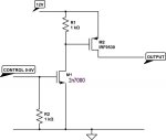
I use a setting like this picture with a LED and resistor instead of the relais and no diode.
http://www.electronics-tutorials.ws/articles/switch8.gif
I just use this simple code
"High 2: Pause 10: Low 2: Pause 10".
Why can't I increase the voltage above 8,8V with pulses?
I use a setting like this picture with a LED and resistor instead of the relais and no diode.
http://www.electronics-tutorials.ws/articles/switch8.gif
I just use this simple code
"High 2: Pause 10: Low 2: Pause 10".
Why can't I increase the voltage above 8,8V with pulses?