08m Help

nyyankeehater

New Member
I am making an LED flasher with multiple flash patterns with the 08m. I know most of the commands but I cant seem to make multiple LED (pins) turn on all at the same time. Every time I try they always turn on in sequence. Please help.
 
Last edited by a moderator:

nyyankeehater

New Member
I am a total noob at thish so please bare with me. any chance of an explanation of all that in noob terms ( the manuals are nice but confusing when u dont know what ur doing)
 
Last edited by a moderator:

eclectic

Moderator
Load this program, then use the Simulator
(the yellow arrow in the programming editor)
Code:
#picaxe 08M

let dirs=%000010110

main:
let pins = %00000001 ; output 0 on

pause 1000 ; pause 1 second

let pins = %00000000 ; all off
pause 1000

let pins = %00000010 ; output 1 on
pause 1000

let pins = %00000000
pause 1000
	
let pins = %00010111 ;4, 2, 1, 0  ON
pause 1000

goto main
Then, change the pin values to

00010011

00000111

and so on

e
 

westaust55

Moderator
Have a look at Appendix D in PICAXE Manual 1 for a start.

Then look at Manual 2 page 97 for the let dirs = command

Finally look at Manual 2 page 98 for the let pins = command

You might also find it good to read up on numbering systems on page 64 of Manual 1
 
Last edited:

nyyankeehater

New Member
This is what I have so far:

Code:
do 
 let dirs = %00000011 ? switch pins 0 and 1 to outputs
 let pins = %00000011 ? switch on outputs 0 and 1
 let pins = %11000011 ? switch outputs 0,1 on
 let pins = %00000000 ? switch 0,1 off
loop
This flashes 2 of what I need but I cant get pins 2,4 to stay on with out flashing. Also, how would I switch on to make pins 2,4 flash and have pins 0,1 stay on?
 
Last edited by a moderator:

hippy

Ex-Staff (retired)
You need to make output pins 4 and 2 also outputs as well as pins 1 and 0 ...

let dirs = %00010111

To get pins 4 and 2 to flash while keeping pins 1 and 0 on requires a three step process; turn on 1 and 0, turn on 4, 2, 1 and 0, turn on 1 and 0 ( which turns off 4 and 2 ), so, without the pauses shown ...

let pins = %00000011
let pins = %00010111
let pins = %00000011
 

kevrus

New Member
you only need issue the DIRS command once unless your code calls for the pins to change from outputs to inputs
so it can be taken out of the do- loop:

main:
let dirs = %00010111 ‘ switch pins 0,1,2 and 4 to outputs

do
let pins = %00000011 ‘ switch on outputs 0 and 1
pause 200
let pins = %00000000 ‘ switch 0,1 off
let pins = %00010100 ‘ switch on outputs 2 and,4
pause 200
let pins = %00000000 ‘ switch 2,4 off
pause 200
loop

ooops, just writing this as hippy posted
 
Last edited:

lbenson

Senior Member
Try this in the simulator--it should show you how to turn on and off any pin or combination of pins using the "let pins =" command. By varying those commands and varying the pauses you should be able to get any combination of flashes you want.
Code:
 let dirs = %00010111 ‘ switch pins 0,1,2,4 to outputs
  let pins = %00010111 ‘ switch on outputs 0,1,2,4
  pause 1000
  let pins = %00000000 ‘ switch 0,1,2,4 off
do 
  let pins = %00000001 ‘ switch 0 on
  pause 500
  let pins = %00000011 ‘ switch 0,1 on
  pause 500
  let pins = %00000111 ‘ switch 0,1,2 on
  pause 500
  let pins = %00010111 ‘ switch 0,1,2,4 on
  pause 500
  let pins = %00010110 ‘ switch 0 off
  pause 500
  let pins = %00010100 ‘ switch 1 off
  pause 500
  let pins = %00010000 ‘ switch 2 off
  pause 500
  let pins = %00000000 ‘ switch 4 off
  pause 500
loop
Note that you could also call a subroutine having set which pins to flash. The following code leaves pin4 on and flashes combinations of 0,1,2.
Code:
dirs = %00010111 ' set pins 0,1,2,4 as outputs
b0 = %00010011  ' on pattern
b1 = %00010000  ' off pattern
b2 = 300        ' pause time

do
  gosub flash
  inc b0
  if bit3 = 1 then ' so we don't try to turn on pin 3
    b0 = %00010001
  endif
loop

flash:
  let pins = b0
  pause b2
  let pins = b1
  pause b2
  return
 

Rickharris

Senior Member
The output pins are controlled by 2 registers (variables) dir sets the direction of the pins - i.e. if they are input or output.

pins turns them on or off so let pins = %00000000 sets all 8 (in this case) outputs to off

let pins = %11111111 sets them all on.

Remember that the first pin (the far right bit is pin 0)
 

eclectic

Moderator
nyy

The sequence is %76543210
but the 08M only has outputs 0 1 2 4

So..
let pins = %00010111 = 4, 2, 1, 0 ON

does that help?
 

nyyankeehater

New Member
yes im getting the hang of it i think. im not at home so i cant try the codes but im still learning
_
 
Last edited by a moderator:

nyyankeehater

New Member
Thank you so much for every ones help. I do have a few more questions about the 08m. first as i said early i have multiple patterns that i want to program into the picaxe so how would I do that and still be able to select the pattern i want to use? Second, would i put a push button switch onto pin 3 to change them. And Last IF I wanted to connect an lcd screen to my project to read which flash pattern was selected, how mush work would that be?
 
Last edited by a moderator:

papaof2

Senior Member
The simplest way to add an LCD is to use one with a serial interface, as it only requires one pin on the 08M. You can get on on Ebay for $16US delivered:
http://cgi.ebay.com/ws/eBayISAPI.dll?ViewItem&ssPageName=STRK:MEWAX:IT&item=230286820803
There are others available there and from other vendors.

To select by a single switch, you could increment the count in a variable each time the button is pressed and use the value of the variable to determine which flash pattern to use. Since the 08M would be busy flashing the LEDs, you would need to use an interrupt (see the SETINT command) to ensure that each button press was detected.

'idea code - not tested
'patternX is the label for the section of code that creates that pattern
'each pattern is assumed to be done in a loop until interrupted

'in your main loop
main:
If countvalue = 0 then pattern0
If countvalue = 1 then pattern1
etc
If countvalue = 7 then pattern7
goto main

pattern0:
'code for pattern0 goes here
do while 1 > 0
let pins = %00010100
let pins = %00000000
let pins = %00010100
let pins = %00000011
let pins = %00000000
let pins = %00000011
loop

pattern1:
'code for pattern1 goes here
do whle 1 > 0
let pins = %00000011
let pins = %00000000
let pins = %00000011
let pins = %00010100
let pins = %00000000
let pins = %00010100
loop

'etc

'using the interrupt capability requires a subroutine named "interrupt"
interrupt:
countvalue = countvalue + 1 and 7
'the above limits countvalue to 0 through 7 (8 patterns)
'if you only have 4 patterns then the last value would be 3
'the number of patterns must be a power of two: 2, 4, 8, 16, 32
return

John
 
Last edited:

nyyankeehater

New Member
im on my cell phone web right now so i cant post a code but i posted one in the thread regarding the fire fighter. do you mind using that code to show me an example of how to change patterns?
________
 
Last edited by a moderator:

eclectic

Moderator
ny,

a few questions, so that others can help you more.

1.What sort of project board do you own?
2.Do you own any other Picaxe chips?
3.Do you own any or all of the following:
Breadboard and wires.
10k and 300 Ohm resistors.
Switches.
Multimeter.
And do you feel confident using them?

It is possible to connect an LCD display, but, with 08M,
you'll then only have three outputs.
If you want more outputs, you'll need to move up to a bigger Picaxe,
such as the 14M, 20M or 18X.

As Papa John said above, you can use Interrupts.
It will work really well.
However, in my opinion, it's best to get the basic connections and programming sorted first.

First, try your program in the simulator.
It works, but it changes very fast.
Try inserting say
pause 500 between each
Let pins = .........


Keep trying; keep working.

e
 

nyyankeehater

New Member
the answer to most of your questions is no, BUT Radioshack is right around the corner and im confident using nething. as of now i have 8 patterns that i am happy with. the lcd was just a thought but not needed.
 
Last edited by a moderator:

eclectic

Moderator
the answer to most of your questions is no, BUT Radioshack is right around the corner and im confident using nething. as of now i have 8 patterns that i am happy with. the lcd was just a thought but not needed.
I'm still a bit lost here.
Could you please answer question 1 : What sort of project board,

then,

read Manual 3 pages 25 and 26.

You'll need to wire a switch correctly to use interrupts.

e
 

nyyankeehater

New Member
what do you mean by project board, like a pcb or perfboard? if that is what you mean then I have a perfboard with copper rings.
 
Last edited by a moderator:

papaof2

Senior Member
For desiging and testing, breadboards are the best solution - you can insert and remove components without soldering/unsoldering and the potential for damage to the components.

Breadboards are inexpensive. Even the smallest one from All Electronics (the $4 one) http://www.allelectronics.com/make-a-store/category/105/Breadboards/1.html is more than big enough for 08M projects. All Electronics also has most of the other components you may need (diodes, transistors, etc) and shipping is a flat $7 regardless of how much you order.

Adding a breadboard to a PICAXE protoboard gives you the best of pre-made and do-it-yourself: the protoboard has all the components needed to connect and program the PICAXE and the breadboard provides space to explore.

Peter Anderson sales protoboards for the PICAXE line: http://www.phanderson.com/picaxe/index.html

My protoboard + breadboard design: http://www.picaxe.us/18proto.html

Brian at Wulfden also sells a protoboard + breadboard unit, among other things. He's closing out his PICAXE items, so this might be a good time to buy: http://wulfden.org/TheShoppe/picaxe/index.shtml

John
 

nyyankeehater

New Member
i do plan on getting a breadboard soon i just wanted to know that i could make the program b4 i spent money that i dont have. (its cold here in the winter). so if i understand you right i need a protoboard to program the picaxe. as far as parts the less i buy online the better.
 
Last edited by a moderator:

Mycroft2152

Senior Member
i do plan on getting a breadboard soon i just wanted to know that i could make the program b4 i spent money that i dont have. (its cold here in the winter). so if i understand you right i need a protoboard to program the picaxe. as far as parts the less i buy online the better.
Welcome to the forum!

Definitely buy a breadboard, it will same you a lot of headaches and speed up your buillding.

As a former Mainer, I lived in Lewiston for 20 years, I can agree that the winters get wicked cold. I like your screen name, unfortunately most of the forum members will have no idea what you are referring too.

Go Sox!

Myc
 

nyyankeehater

New Member
Welcome to the forum!

Definitely buy a breadboard, it will same you a lot of headaches and speed up your buillding.

As a former Mainer, I lived in Lewiston for 20 years, I can agree that the winters get wicked cold. I like your screen name, unfortunately most of the forum members will have no idea what you are referring too.

Go Sox!

Myc
thanks for the welcome i just went and got a bread board today and as soon as i get the program done i will order the picaxe and other parts. btw where in the northeast are you now?
 
Last edited by a moderator:

eclectic

Moderator
nyh

Firstly, write out your eight patterns.
Start with something like this:
Code:
pattern0:
let pins = %00010100
pause delay
let pins = %00000000
pause delay
let pins = %00010100
pause delay
let pins = %00000011
goto main

pattern1:
let pins = %00010100
pause delay
let pins = %00000011
pause delay
let pins = %00000000
pause delay
let pins = %00000011
pause delay
goto main
and so on up to pattern7

And another question, to help clear my confusion.

Have you actually got a working Picaxe circuit?

e
 

nyyankeehater

New Member
no i do not have a circuit this is my first with any pic. ill post the codes tomorrow morning.
 
Last edited by a moderator:

nyyankeehater

New Member
Code:
let dirs = %00010111
pattern0:
let pins = %00010111
let pins = %00000000
let pins = %00010111
pause 50
let pins = %00000000
pause 50
goto main 

pattern1:
let pins = %00010100
let pins = %00000000
let pins = %00010100
let pins = %00000011
let pins = %00000000
let pins = %00000011
goto main

pattern2:
let pins = %00010011
let pins = %00000011
let pins = %00010011
let pins = %00000011
let pins = %00000111
let pins = %00000011
let pins = %00000111
let pins = %00000011
goto main

pattern3:
let pins = %00010111
pause 250
let pins = %00000011
goto main

pattern4:
let pins = %00010001
let pins = %00000110
let pins = %00010001
goto main

pattern5:
let pins = %00010101
let pins = %00010110
let pins = %00010101
goto main

pattern6:
let pins = %00010111
pause 250
let pins = %00010100
goto main 

pattern7:
let pins = %00000011
let pins = %00010100
pause 80
let pins = %00010100
let pins = %00000011
goto main
for the record I did all of the patterns seperate so each one die have its own "main"
 
Last edited by a moderator:

eclectic

Moderator
Nyy, in my opinion
I think that you need to get a real Picaxe circuit up and running.

Here are my recommendations, for boards.
I'm just using Sparkfun's site as an example,
obviously US users can give you lots more advice.

1. Depending on your computer, either
A Serial cable
http://www.sparkfun.com/commerce/product_info.php?products_id=8313

or a USB programming cable
http://www.sparkfun.com/commerce/product_info.php?products_id=8312


2. A couple of 08M chips and this board
http://www.sparkfun.com/commerce/product_info.php?products_id=8321


3. 18X chip and this board
http://www.sparkfun.com/commerce/product_info.php?products_id=8330

The 18X has eight outputs, and will allow much larger programs.

You could buy other items locally.

e
 

eclectic

Moderator
Reply part 2.
With an 18X, and eight outputs:

I've taken this program from the sample files that come with the programming editor.
I've only made three changes.

Try it in the simulator. It looks very good.
It looks even better in real life.

e
Code:
'led_test.bas
'Generate pretty LED patterns.
'Author unknown, modified by CPS May '98.

'This is the test program downloaded to
'Revolution's Stamp Controller to test the
'pcb for correct operation before despatch.

'Load some pretty patterns into EEPROM memory.
#picaxe 18x '******
eeprom ($0,$0F,$F0,$3C, $C3,$18,$3C,$7E, $FF,$E7,$C3,$81)
eeprom ($0,$03,$06,$0C, $30,$60,$C0,$60, $30,$0C,$06,$03, 0)

'Define symbols
symbol i = b0
symbol j = b1
symbol k = b2

'Define time delays
symbol const1 = 50
symbol const2 = 150

'Main program

'The let dirs= line is only required with the Stamp
'For PICAXE systems comment out the line using a '

'let dirs = %11111111            'all pins output!

'change Loop to Looper **********
Looper:   For i = 0 To 7          'bar climbing
           pause const1
           high i
        Next i

        For i = 0 To 7          'and disappearing...
           pause const1
           low i
        Next i

        Let j = 1               'single light moving up
        For i = 0 To 7
           Let pins = j
           pause const1
           Let j = j + j
        Next i

        Let j = 64              'and rolling back
        GoSub roll_back
        
        Let j = 3               'bar climbing up
        For i = 0 To 6
           Let pins = j
           pause const1
           j=j+j|1
        Next i

        j = 127                 'and rolling back
        GoSub roll_back

        For i = 0 To 24         'some more effects
           read i, j
           Let pins = j
           pause const2
        Next i

        goto looper              'loop forever!
'change Loop to Looper

'sub-procedures
roll_back:
        For i = 0 To 6
           Let pins = j
           pause const1
           j = j / 2
        Next i
        Return
 

nyyankeehater

New Member
Can I ask why its so important to have a circuit running b4 i do this project. Im not new to electronics just PICs.
 
Last edited by a moderator:

nyyankeehater

New Member
Reply part 2.
With an 18X, and eight outputs:

I've taken this program from the sample files that come with the programming editor.
I've only made three changes.

Try it in the simulator. It looks very good.
It looks even better in real life.

e
Code:
'led_test.bas
'Generate pretty LED patterns.
'Author unknown, modified by CPS May '98.

'This is the test program downloaded to
'Revolution's Stamp Controller to test the
'pcb for correct operation before despatch.

'Load some pretty patterns into EEPROM memory.
#picaxe 18x '******
eeprom ($0,$0F,$F0,$3C, $C3,$18,$3C,$7E, $FF,$E7,$C3,$81)
eeprom ($0,$03,$06,$0C, $30,$60,$C0,$60, $30,$0C,$06,$03, 0)

'Define symbols
symbol i = b0
symbol j = b1
symbol k = b2

'Define time delays
symbol const1 = 50
symbol const2 = 150

'Main program

'The let dirs= line is only required with the Stamp
'For PICAXE systems comment out the line using a '

'let dirs = %11111111            'all pins output!

'change Loop to Looper **********
Looper:   For i = 0 To 7          'bar climbing
           pause const1
           high i
        Next i

        For i = 0 To 7          'and disappearing...
           pause const1
           low i
        Next i

        Let j = 1               'single light moving up
        For i = 0 To 7
           Let pins = j
           pause const1
           Let j = j + j
        Next i

        Let j = 64              'and rolling back
        GoSub roll_back
        
        Let j = 3               'bar climbing up
        For i = 0 To 6
           Let pins = j
           pause const1
           j=j+j|1
        Next i

        j = 127                 'and rolling back
        GoSub roll_back

        For i = 0 To 24         'some more effects
           read i, j
           Let pins = j
           pause const2
        Next i

        goto looper              'loop forever!
'change Loop to Looper

'sub-procedures
roll_back:
        For i = 0 To 6
           Let pins = j
           pause const1
           j = j / 2
        Next i
        Return
yeah that looks cool but I have NO use for it as far as this project goes. This project is an attempt to save my friend a lot of money on warning lights (hes a firefighter). Also I start my Firefighter training in a few months and dont want to spend a sh!t ton of money on lights that I want but dont really need when I feel that I can bulid what im looking for for a fraction what I can buy them for.
 
Last edited by a moderator:

nyyankeehater

New Member
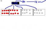
This is just a quick and crappy paint shop of what i looking to do (this blue lines are meant to show which lighthead goes with which output) [ just to be sure red dots are red leds and grey are white leds :D]
 

Attachments

Last edited by a moderator:

hippy

Ex-Staff (retired)
Can I ask why its so important to have a circuit running b4 i do this project. Im not new to electronics just PICs.
The main advantage of having some sort of circuit working before starting the project proper is so you can become familiar with the PICAXE actually running code and controlling outputs. Best to discover any misunderstandings early on rather than when you've built the project and find you have to change it.

Having the real circuit designed ( even if not built ) is often important because it will define which output pin controls what, otherwise it can mean software is designed for a hardware configuration which isn't the same as what it ends up being. This can lead to major software changes and it is possible that in some cases the hardware doesn't match what the PICAXE supports.

If confident, there's no reason not to write the code, build the hardware, plug a PICAXE in and have it work. Experience on the forum however show that some people who take that approach then hit the buffers and report things like "download doesn't work", because it's the first time they've used a PICAXE and have made some mistake or used an assumption which isn't valid.

yeah that looks cool but I have NO use for it as far as this project goes.
Are you sure ? It does what you are asking for and demonstrates a quite effective way of sequencing patterns as you want.

This ties in with having the circuit before completing the project; you can try various code techniques to see what works best for you.
 

eclectic

Moderator
Nyy
I see that you've read this thread:
http://www.picaxeforum.co.uk/showthread.php?t=10793&page=2

therefore, you'll appreciate that you will require a lot
more than an 08M to power banks of high output LED's.

I've done a little work on rear-lights for a bike, using sequenced
flashing on four and eight LED units.
The programming was the easy bit. It only took a few minutes.
By far the most difficult tasks were the physical construction and testing.
And, this was with a 4.5 volt battery-supply and 20mA high-power LED's

Your project, requires daylight-visible flashers, in an automotive environment.
It may need several Amps current.
It has a higher level of “mission-critical” and “safety-critical” factors.

From my point of view, it will require a great deal of reliability-testing,
using actual components.

I wish you good fortune in your endeavours.

E
 

nyyankeehater

New Member
not trying to be argumentive but i have powered 1.5v leds with nothing but a resistor off a cars 12v supply with no problems
 
Last edited by a moderator:

Mycroft2152

Senior Member
Nyan,

Creating a working program in the simulator is the least expensive method to start. That is only the first step.

You really need to find out how many LEDs you really need to be visible. Make up a single "lamp" and toggle it with a switch. My guess is that you will need at least 40 per "lamp" (160 total). From there.you can determine the current needed to drive the LEDs and size the transistor accordingly.

But before you go any further, cost out the parts you think you need to build your circuit. Don't forget to include the cost of the perf board, the project box, fuse holder. mounting brackets, resistors, transistors, etc.

I'm not sure how much money you will actually save. The ebay flasher is looking better and better.

The PICAXE is the easy part.

Myc

Western MA
 

hippy

Ex-Staff (retired)
not trying to be argumentive but i have powered 1.5v leds with nothing but a resistor off a cars 12v supply with no problems
That is the easy part; switching lights under PICAXE control is a little harder, especially if using high current LEDs. It is however possible to do.
 

nyyankeehater

New Member
well thank you for everyone's help it is greatly appreciated. I'm still a little confused on the SETINT command. How and where exactly do I use it to activate a pattern every time a push the button?
 
Last edited by a moderator:
Top