Hi,
In making a binary clock with the DS1307 as the time keeper, I have discovered that over a period of about 10 days, the time is off by almost 30 seconds. I admit that's not a huge amount, but I like my timekeepers accurate, hence the wristwatch on my arm and wall clock in my den that are corrected by the WWVB time signal in Colorado...
Having been a powerplant operator for almost 32 years, I know that the frequency of the grid is very accurately controlled - it does wander by a VERY small amount over the day, but is returned to a balance, by law, daily.
I'm thinking of using the grid frequency as the 60Hz input to my 28X1 clock program. I know that I could use various means to accurately divide down the 60Hz to 1 Hz (7490's, 4017's or even a 4040 to name a few) but I want to keep it all Picaxe - Using an 08M as a divide-by-60 chip feeding the input to the 28X1.
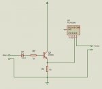
Playing around with an 08M (see schematic) and the following code, produced results that weren't too bad, but still not perfect:
It runs slow, so I figure in the time it's taking to execute the code, it's missing some of the input pulses. Before someone asks, the schematic is based on the chip being on the AXE091 development board, so while not shown, the input resistors for serial input (pin2), are actually there...
I read elsewhere on this forum on the uses of the interrupt routine, so I modified my code to:
As a test of accuracy, I used a very simplistic method - I kept restarting the circuit until the LED blinked on at the exact same time as my watch second hand advanced. In the short term, it seems bang on, but letting it run over-night reveals that the LED and second hand are no longer in sych (I'm betting on my watch being the accurate half here). This, of course, doesn't tell me if the Picaxe is running slightly fast or slightly slow. I hooked up my scope, which has a counter function, to pin7 (out0) to count the pulses against a stopwatch. Over the course of 60 minutes, it was perfect (3600 counts).
I thought that maybe line noise was adding some extra counts over time, but I have never seen any noise on the scope.
So, is this a viable means of using an 08M as a divide-by-60 ?
Should this interrupt code work, or am I missing something ??
Thanks, John.
In making a binary clock with the DS1307 as the time keeper, I have discovered that over a period of about 10 days, the time is off by almost 30 seconds. I admit that's not a huge amount, but I like my timekeepers accurate, hence the wristwatch on my arm and wall clock in my den that are corrected by the WWVB time signal in Colorado...
Having been a powerplant operator for almost 32 years, I know that the frequency of the grid is very accurately controlled - it does wander by a VERY small amount over the day, but is returned to a balance, by law, daily.
I'm thinking of using the grid frequency as the 60Hz input to my 28X1 clock program. I know that I could use various means to accurately divide down the 60Hz to 1 Hz (7490's, 4017's or even a 4040 to name a few) but I want to keep it all Picaxe - Using an 08M as a divide-by-60 chip feeding the input to the 28X1.
Playing around with an 08M (see schematic) and the following code, produced results that weren't too bad, but still not perfect:
Code:
# picaxe 08M

'60 Hz conditioned signal fed to in1 (pin6)
'out0 (pin7) delivers 1 Hz square wave
'see 1Hz Extractor.dsn

b0=0

main:

if pin1=1 then
	b0=b0+1
endif

if b0>119 then
	goto tog_LED
endif

goto main


tog_LED:

b0=0

toggle 0

goto mainI read elsewhere on this forum on the uses of the interrupt routine, so I modified my code to:
Code:
# picaxe 08M

'60 Hz conditioned signal fed to in1 (pin6)
'out0 (pin7) delivers 1 Hz square wave
'see 1Hz Extractor.dsn

b0=0

setint %00000010,%00000010		' set interupt for in1 (pin6)

main:

if b0>29 then				'next 3 lines count 30 +ve half-waves of AC,
	toggle 0				'toggles out0 and resets counter back to 0
	b0=0
endif

goto main

interrupt:

if pin1=1 then interrupt		'wait until in1 is low
b0=b0+1					'increment b0 by 1
setint %00000010,%00000010		're-enable interupt
returnI thought that maybe line noise was adding some extra counts over time, but I have never seen any noise on the scope.
So, is this a viable means of using an 08M as a divide-by-60 ?
Should this interrupt code work, or am I missing something ??
Thanks, John.
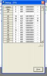
Attachments
-
 77 KB Views: 69
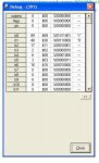
Last edited: