pjrebordao
Senior Member
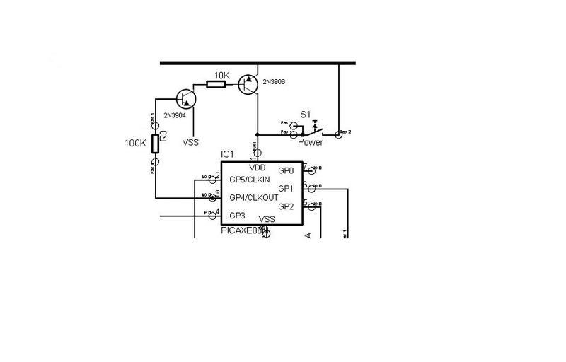
In one of my current projects, I'm trying to implement a simple circuit to enable an 08M to power itself off.
My limited electronics experience and expertise has led me to believe that a simple setup involving a Darlington could do the trick, but so far it failed to do so...
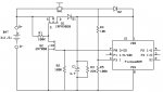
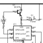
Looking at the attached circuit, I'll explain my idea:
Pressing the S1 pushbutton would start the 08M, it's first line of code would be "high 4", thus "turning on" the Darlington and ensuring that power is present at VDD, even after the button is released. In practice, as soon as you release the button, the 08M stops...
Can anyone give me a clue on what's going on ?
My limited electronics experience and expertise has led me to believe that a simple setup involving a Darlington could do the trick, but so far it failed to do so...
Looking at the attached circuit, I'll explain my idea:
Pressing the S1 pushbutton would start the 08M, it's first line of code would be "high 4", thus "turning on" the Darlington and ensuring that power is present at VDD, even after the button is released. In practice, as soon as you release the button, the 08M stops...
Can anyone give me a clue on what's going on ?
Attachments
-
 19.4 KB Views: 168
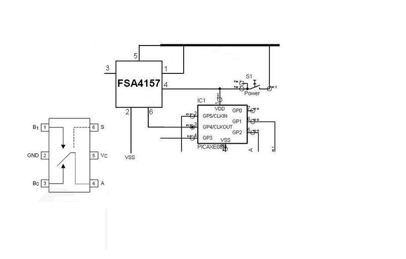
") I thought of a single mosfet low-side switch but never tried it. Not sure if there is current path from Battery+ to Battery- through Vdd, P1, R1, with the power off. ???
I thought of a single mosfet low-side switch but never tried it. Not sure if there is current path from Battery+ to Battery- through Vdd, P1, R1, with the power off. ???