14X2

Dave E

Senior Member
Does anyone know if there are plans for smaller X2 chips? I would like to see a 14X2. A 20X2 works for replacing a 14M but looks a bit unprofessional.
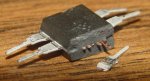
See attached photo.

Or maybe the manufacturer could just add perforations across the chip between the pins and we could just snap off what we don't need. That way we could have:
20X2
18X2
16X2
14X2
12X2
10X2
08X2


What do ya'll think?

Dave E :rolleyes:
 

Attachments

MartinM57

Moderator
Or maybe the manufacturer could just add perforations across the chip between the pins and we could just snap off what we don't need.
What do ya'll think?
Dave E :rolleyes:
I think you've been on the moonshine too much. But maybe an email to Microchip Future Development Department could be worth a shot...
 

womai

Senior Member
The issue there is you need a suitable Microchip PIC device to base the Picaxe on. The small-pin-count devices tend to have less flash memory, less RAM, and less peripheral options that the larger devices. That means there is no way to fit all the capabilities of e.g. a 28X2 into any of the 8-pin devices. Another obstacle is that e.g. the 8-pin PIC12Fxxx don't have self-write capability so they can't modify their own program memory - the Picaxe program needs to be stored in the (small, 256 byte) user EEPROM area. The 12F683 is already the top of the line - and that gives you the 08M...
 

Dave E

Senior Member
It Works....14x2

IT'S ALIVE!!!!!

LOL LOL LOL.............
See attached.

All you need is a 20X2 minus the last 3 sets of pins. It is working, see the LCD. I scored the IC with a file and broke off the last 3 sets of pins.

Now where did I put that jug of moonshine.:rolleyes:

Dave E

P.S.
Do not try this at home. "hic"
There is NO guarantee that this chip will keep working. "hic"
(but I had to try)

I hope REV-ED doesn't get mad at me.
 

Attachments

Last edited:

MPep

Senior Member
YOU DID WHAT???????????????:eek::eek:
Well, it definitely won't be a recommended method!!!!!!!!!
What you do with your money is up to you, I suppose.

Well done for trying it.:D And providing proof.
 

womai

Senior Member
Not too surprising actually that it works. Most likely the actual chip is tiny compared to the huge DIP package, and sitting in the very center of the package - the rest is bond wires and lead frame. So as long as you don't rip off any bond wires accidentally cause some short when you cut the package, it will keep running.
 

Andrew Cowan

Senior Member
Wow! Better send an email to microchip and see if they want you to convert a whole batch of chips for them :).

Well done for having the nerve to try it! You are now the owner of the first (purely ornamental) 6 pin PICAXE!

Andrew
 

hippy

Technical Support
Staff member
I hope REV-ED doesn't get mad at me.
Bravo for having the courage to try it.

Most IC's have a small square of silicon in the centre and there are just thin connections to the leg metal which then run off to form the external pins. So cutting an end off - if done carefully enough - should just slice through the internal pin metal without damaging the chip. The ESD diodes will be on the silicon itself so the outcome is no worse than leaving those pins floating.

If you can find an old Eprom with a quartz window you can actually see the incredibly thin wires which link the silicon to the connectors which go to legs ..


The usual method of getting a 20-pin chip in a 14-pin socket is to bend the excess legs up or snap them off, but it seems major amputation in this case has workd.
 

kevrus

New Member
All we need now is for the connections to the silicon to be elasticated then we could move chip pins to wherever we wanted on the PCB..no need for DIL packaging restrictions!!

P.S., I tried it with an 8 legged spider but it immediately lost the ability to walk
 

hippy

Technical Support
Staff member
PICAXE-08X2 ?

If you can cut six legs off the bottom, it's a reasonable bet you can cut six off the top, leaving an 8-pin lump. Of course you cannot ever reprogram it once done.

Executing DISCONNECT as the first command will stop the PICAXE entering download mode but may mean rather long start up times until the first command is executed in an electrically noisy environment. Power would have to be via input pins and rely on the internal clamp diodes as bridge rectifiers. An additional 'advantage' to that is you can have a self-destructing chip by setting the +V connection output low ;-)

Not really practical and may not work but something perhaps for a rainy day. Best to try with the pins bent first so it's potentially recoverable.

Tech-Supplies and dealers provide a wide range of PICAXE chips to replace those damaged in surgery or those which have gone through the grinder.
 

Texy

Senior Member
Yes, this has been discussed many times before (myself included;)).
Having a smaller footprint chip (not SM), that is faster, but more importantly, has more program memory, would be very usefull indeed, but as has already
been pointed out, it is in the lap of the God's - ie a suitable chip being produced by Mircochip themselves.

Texy
 

Dave E

Senior Member
I have seen a few exploded ICs :rolleyes: to know that the actual working part of the chip is, as mentioned above, very small and centered so I had an idea that it might actually work.
At least we now have proof of concept.

If anyone is in need of 14X2s let me know. For a nominal fee..........

This does bring up a question though, should unused pins be left as is or should they be set as inputs or outputs, outputs high or low or pulled up?

Dave E
 

hippy

Technical Support
Staff member
In most cases inputs and input/outputs can be left floating.

Outputs should be left unconnected, it's generally recommended good practice to pull-down inputs to 0V, genuinely input-only ( as per hardware on the PICmicro not by definition as PICAXE input pins ) can be connected directly to 0V.

As to setting input or output, output is sometimes suggested, but I consider if something changes that to an input and there's no pull-down it's left floating, so I wouldn't personally do that if I were concerned.

There's previous discussion on the subject on the forum. It only really becomes important if designing commercial product or striving for lowest power operation.
 

Dave E

Senior Member
I know, I know.
It hurt, but once the idea was out there ..... what could I do?
Had to take one for the team. But hey, it is still running.


Thanks for the input hippy. I will leave the amputated stubs as is.

Dave E
 

Attachments

Last edited:

nbw

Senior Member
Good point Dippy. If you chop a 28X2 in half, will it become 2 x 14M??? or 2 x 14X1??

Ah, PICAXE physiology - too much on a Weds morning!
 

MPep

Senior Member
Not too surprising actually that it works. Most likely the actual chip is tiny compared to the huge DIP package, and sitting in the very center of the package - the rest is bond wires and lead frame. So as long as you don't rip off any bond wires accidentally cause some short when you cut the package, it will keep running.
You are right that the silicon inside is tiny compared to the package. It is all the legs that take up space. Now, exactly where the silicon is, I don't know. How small can you go????:D
 

Dippy

Moderator
Just gently file the top off and have a look.

In fact, at one end of the DIP package there is a micro-catch. If you use a microscope and fine-point tweezers and pull it gently it releases the catch.
Then you can lift the top like the bonnet/hood of a car and see underneath.
 

MartinM57

Moderator
...and on the right hand side of the silicon chip (with the micro-catch on the right) you'll see a small capsule labelled in very small red writing "WARNING - CONTAINS SMOKE - DO NOT LET OUT"
 

Dave E

Senior Member
:eek: latch?
I could have done a much better job had I known about the latch.
I was very worried about getting too close to the smoke capsule. I knew it was in there somewhere but I didn't know exactly where it was in relationship to the die.

When I program the 14X2 it still shows up in the PE as a 20X2.?????
This may mean that 2 halves of a 28X2 will grow to become 2-28X2s. I will let someone else test that theory. I won't do it again. As of now the 14X2 is still just a 14X2. No signs of self healing but it is still working. Since it wasn't divided in half it may not regenerate properly.

Dave E
 

Dippy

Moderator
Oh, is that a smoke capsule? My Ebay magnifying glass distorts slightly.

I had assumed that was the new Auto Fire Extinguisher that they install now after hearing that Manie had started using electronics.
Maybe that's just in MOSFETs though :)
 

Michael 2727

Senior Member
That micro-catch is the lever arm for the 4MHz Clock governor, don't fiddle with it.
And if you pop the hood/bonnet watch out the mainspring doesn't fly out and hit
you in the eye, wear safety glasses.

What ever happened to Moore's Law at Microchip, did they lose that memo ?.
I've been waiting for an 08X100 monster for ages, still waiting, waiting ~ ;o(
 

Dippy

Moderator
Maybe they are spending the pennies on the ds and 32 instead?
I can;t imagine any flashy toy manufacturer wanting to use DIP8 PICs now.
 

hippy

Technical Support
Staff member
With respect to Moore's Law and Microchip; they've gone from 4MHz to 8MHz to 64MHz in quite a rapid time, and finally got those speeds from oscillators on-chip, which isn't bad going. Not sure when or what the next speed jump will be and most probably won't want it with a massively increased current draw or needing a heatsink !

I think there's probably a natural limit for capabilities on all microcontrollers for hobbyists, simply because of number of legs and packaging formats. Beyond a certain level of 'oomph' the disparity grows between what a chip is capable of and the usability of that capability.

There's less need for 1GB memory and 1GHz speeds on an 8-pin chip than on larger ones so little incentive to provide for that other than as an 'easy add' as a side product of other developments elsewhere.

There may one day be an 08X100 - but it'll probably be so small you cannot see it ;-)
 

Dave E

Senior Member
Very sensible reasoning, hippy.
However, even an 08X or 14X would be useful. Mainly for program space. The 08 and 14 are darn useful sizes. A majority of my projects use just those 2 chip sizes. Even 1k of memory would do everything I need to do with a 8 or 14 pin micro. I know that a 20X2 is just a few $ more than a 14M but I have this thing about waste of any kind even if it is only a couple of IC pins.
Don't take this wrong. I think Picaxe micros are the next best thing to sliced bread. Just wishful thinking.:rolleyes:

Dave E
 

manuka

Senior Member
Waste you say? Some time back I mentioned a 6 pin "10F" micro, & now ponder that even a 08M may also cope with a couple of legs less. The resulting "06M" then offers just Pins 0,1 & 4, but these may be enough for skinflints !

Mmm- this reminds of a NASA 1960s moon shot programming joke (back in a crucially weight dependant era),of essence that only the punched card holes were actually going aloft.
 

MPep

Senior Member
True enough about the 10F range. However, the 6 pin variants are SMDs only. There is a DIP version but, you guessed it, in a 8pin package.
About the only time I have ever seen a 6pin DIP (and even a 4pin DIP) is using opto-couplers.
 

hippy

Technical Support
Staff member
The 10F, 6-pin, PICmicros are a good example of 'you don't need to be able to do much if you've only a few I/O pins' design; not enough Flash nor Ram to run the PICAXE firmware.
 

inglewoodpete

Senior Member
I think the cut-down 20X2 to 14X2 has great potential. I could really use a 14-pin PICAXE with some grunt.

Having a look at the package, its a pity that the i2c and hserial pins would have to be sacrificed to get the sawn-off 14-pin package.

~sigh~ wouldn't it be nice if MicroChip produced a suitable candidate 14-pin PIC:rolleyes:

Edit: Just checked Microchip's product catalogue: the proposed 12F1823 has some potential! 14-pin, self writing flash, SPI/I2C, 32 MHz. Now if RevEd has the inclination.....
 
Last edited:

Technical

Technical Support
Staff member
Unfortunately the 14pin 16F1823 has a pretty small memory size and so is not suitable for any type of 'X/X1' status -it just hasn't have the RAM or program memory space (same as existing 14M in fact). However if a larger memory capacity in the same format is ever released...
 

inglewoodpete

Senior Member
Unfortunately the 14pin 16F1823 has a pretty small memory size and so is not suitable for any type of 'X/X1' status -it just hasn't have the RAM or program memory space (same as existing 14M in fact).
Thanks for the response. I did wonder about the amount of firmware space. I also thought that most of the programme and data space for music/sound in the M series could be put to better use. Just include the i2c slave function... Probably still a tall order.

However if a larger memory capacity in the same format is ever released...
Good to see you're tempted:)
 

manuka

Senior Member
Aside from this poor mans PIC foundry, it's worth keeping an eye on Microchip's listings for features of their available & future PIC offerings. The ~5 yo. PIC12F683 (our 08M engine of course) looks akin to their planned 12F1822 & 12F617 etc.

But never mind "trimmed chip" approaches-scope exists of course for cleaner doubled layouts. Fancy a 16M? Just place 2 x 08Ms end to end (with suitable wiring) for immediate memory & feature boosts. Even trim off 2 pins, fit them into a DIP14 IC socket & you'd have a 14M with real attitude.
 
Top