Breadboards: Tips, Tricks and Photos

Mycroft2152

Senior Member
The use of breadboards is a topic that keeps coming up on the forum. I ran a forum search and found a number of references hidden within many threads. It seemed that it would be handy to have on thread where breadboard info could be easily accessed.

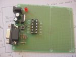
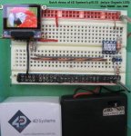
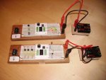
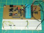
Well here it is! A place for breadboard tips, tricks and photos. Add to it! Post photos of "My breadboard".

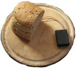
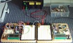
To start it off, here;'s a photo of the most famous breadboard of all:

 
Last edited:

Dippy

Moderator
Breadboard info? It's a plastic thing with holes into which newbies poke things, blow up their PICAXE and scream that they have been sent a duffer.

I hope Stan does some more piccies with new felt-tip pen marking and tidier wiring :)

Seriously though, they are darned useful when used carefully. But as to a 'gallery' of famous breadboard pictures... oh dear. If Stan saw my latest one with no felt-tip and no labels he'd have a fit. And I'm still using the same one that I bought in 1867.
 

Mycroft2152

Senior Member
Come on Dippy, post the photos. Your fans await!

Seriouly, show all the good, the bed and the ugly breadboards.
 
Last edited:

Tom2000

Senior Member
I've modified one of Peter Anderson's 18X protoboards. Before and after photos attached.

This has been about the handiest breadboard in my collection. Of course, it's particularly handy for 18X experiments, but I've also plugged 08Ms and 28X1s into the breadboard, just stealing power and the download circuit.

I've breadboarded lots of non-micro stuff on it too, including an RF mixer, all sorts of miscellaneous transistor and op amp stuff, and even a PIC 18F2431 DSP experiment.

I've described my mods here.

Tom
 

Attachments

manuka

Senior Member
This surely is a big tease since I've enthused enough regarding solderless prototyping to last several lifetimes. For those who may have missed my raves (!), check the two extremes below. Small flexible rugged jumper links (sold in NZ by Surplustronics at ~5¢ each) have been a further BB productivity aid, & I highly recommend them for initial trials & schools work. Electronic newbies often have immense hassles stripping normal wires of course...
Stan
 

Attachments

Last edited:

demonicpicaxeguy

Senior Member
comon Dippy, pretty please with a picaxe on top?

i'll show you mine if you'll show me yours....... :)

i picked up the one above about 5 years ago some a mate of mine that was at tafe, aparently they threw out a whole heap of them he grabbed the lot gave e a couple we later worked out why they threw some out, it was because some of the strips weren't grabbing as well as they should jave been
on the board is a pic18lf452 with 2X 24lc256's the lcd and an opamp i haven't gotten around to wiring up yet


above is a pic18f4550 with usb running, next to the black capacitor is the diy usb breadboard plug and yes the sdcard part of things is running and running very well after a lot of trouble ,the board the sd card is on where you can see the liberal amounts of solder is where the pins underneath have lifted the copper track and broken it (it's had about 2 years of solid use with many many different cards
 

Dippy

Moderator
Blimey, what a lot.

Sorry, all my SD stuff is s/m pcb. Apologies, sorry I can't join in with your spaghetti.

Love the gaffer/duct/duck tape round yer bench :)
 

demonicpicaxeguy

Senior Member
thats 2 of the 8 bread boards i've got,

the table i've got those sitting on is actaully a long bench made of pine 2X4 wood with chipboard table top's
the gaffer tape holds this decorative strip on the front that was glued on, i don't think it was meant to last because it didn't stay glued for very long

if anyone remembers who olivetti is i've still got a grey ps/2 keyboard thats now probably about 12 years old no i think, and i'm yet to find a better one,
it's the one shown in the top photo
 
Last edited:

Tricky Dicky

Senior Member
This is the arrangement we use in our place. A plug in daughter board with all the download components and PICAXE 08M on the board, the slide switches allow those pins which double up as inputs or outputs to be configured either way. Its simple for the kids, inputs on the left and outputs on the right. We also have a PICAXE 18 version that includes the reset switch circuit and uses a LIF socket for the PICAXE 18.

The photo shows two breadboards wired up as a simple IR transmitter and receiver.

Richard
 

Attachments

Last edited:

Dippy

Moderator
Thats nice and neat Tricky. Makes DPGs and Stan's look a bit untidy :) (You ain't seen mine :()

By the way, those green terminals; are they the Pheonix or Camden 'rising clamp' types?
If so, well done, so much more reliable than the bendy metal types - and only a few pennies more.
If not, may I take this opportunity to recommend the Camden or Pheonix 'rising clamp' type; so much more reliable than the bendy metal types - and only a few pennies more.

For those vaguely interested:
http://www.farnell.com/datasheets/36100.pdf
(an example of the mid-size green pcb terminals)

For those not, I'm sure there's a page on Ebay.

Seriously though, the quality is excellent especially where you are doing a lot of in-out with your wire.

Apologies, I've digressed from the Breadboard Gallery.
 

Mycroft2152

Senior Member
Thats nice and neat Tricky. Makes DPGs and Stan's look a bit untidy :) (You ain't seen mine :()

By the way, those green terminals; are they the Pheonix or Camden 'rising clamp' types?
If so, well done, so much more reliable than the bendy metal types - and only a few pennies more.
If not, may I take this opportunity to recommend the Camden or Pheonix 'rising clamp' type; so much more reliable than the bendy metal types - and only a few pennies more.

For those vaguely interested:
http://www.farnell.com/datasheets/36100.pdf
(an example of the mid-size green pcb terminals)

For those not, I'm sure there's a page on Ebay.

Seriously though, the quality is excellent especially where you are doing a lot of in-out with your wire.

Apologies, I've digressed from the Breadboard Gallery.
That wasn't a digression Dippy. Put your eBay reading glassses back on. the title of this thread is Tips, Tricjk, and photos.
 

Mycroft2152

Senior Member
Tricky Dicky,

Nicely done!

One sugggestion for the white pcbs is to apply component labels to the top using the Toner Transfer method.

Myc
 

Tricky Dicky

Senior Member
Dippy

You are correct they are the Camden rising clamp type and a nice bit of kit they are. The boards in the photo were the prototype ones I designed as a project whilst on a course. I have to hang my head in shame though and admit I was only able to use quality because someone else was paying for it. When we went into full production back at school we also went cheapo both on the terminals and slide switches.

Incidently, Prof. John Martin from Salford Uni will be featuring my design in an article in D&T Practice sometime this summer and the D&T Association will be making it available for free download.

BTW does anyone know where the term "breadboard" comes from, my students constantly ask me? I know the term in electronics preceded the now familliar plastic board full of holes and I have a feeling it has something to do with the early days of electronics when prototype circuits were produced by soldering copper wires to pins driven into wooden boards. Can anyone remember that far back or am I giving away my age.

Richard
 

hippy

Ex-Staff (retired)
BTW does anyone know where the term "breadboard" comes from
My guess would be from someone needing to build a circuit in the days of bakelite and deciding to grab the kitchen breadboard and hammer some nails in it to fasten components to.

I bet the evening meal involved some cold glares :)
 

manuka

Senior Member
Dippy - how about this "byte slicer" wireless version !


Check a very lucid BB wiki =>http://en.wikipedia.org/wiki/Breadboard.

Point-to-point construction was the way most electronics circuits were constructed before the 1960s, typically using tag or terminal strips fastened to insulating boards. Such assembly was the hall mark of intensively repetitive unskilled factory mass production assembly,as labour was cheap compared with the VERY expensive end products-an early B&W valve TV (perhaps the zenith of the "art") cost several months income then, & military grade WW2 era radios could cost even more...

Most hobbyists simply used a breadboard sized piece of wood to which they screwed such connection points. Circuit size was incidental,as often a "bigger the better" culture prevailed. All my (pre & early teen 1960s) work - mostly valve based-was done this way, with circuits similar to the nice pix above.

When aluminium cabinets & chassis were king it was also common to "ugly construct" directly to valve & terminal sockets. (Note the pre 1970s sharp ended carbon composition resistors & high VW caps!)
 
Last edited:

Dippy

Moderator
Tricky Dicky: "I have to hang my head in shame though and admit I was only able to use quality because someone else was paying for it."
- please hang it now and also hang your accountant too.

Terminal blocks PCB:-
Camden High Quality 3 way 31p vs A.N.Other.low.quality(Beijing?) 26p. example from Rapid.

Ah well, I guess that 5p saved will pay for yet another nail in the coffin for European jobs. I hope your accountant is proud.
 
This is a picture of my latest creation, I have used it with 8 and 28 pin Picaxes and works fine. The connecting wires are hand made and I never seem to have enough.
Manuka's photo shows a very nice package from Surplustronic-NZ. I tried to order from them but the ordering system accepts only orders from New Zeland. I will be glad to send an international Money Order to any body in New Zeland that is willing to get it for me and ship to the US.
If anobody is willing to help, get me at:
ajr at rochester.rr.com
Andres
 

Attachments

manuka

Senior Member
Who can resist a request like this- anyone else in US want some too for Marmitas (who has already asked for 3 sets of 75 leads) to on-forward? I'll check p&p next week, but anticipate each lead will be ~US 10¢ by the time it arrives in your far flung BB.
 
Last edited:

Grant Fleming

Senior Member
Thanks Beanie Bots and Dippy,
In the online store I had only looked in PICAXE/Project Boards-not found there, I hadn't used the 'search' feature before but can see now with the product # it's quite effective!
I just need to ask my Australian supplier (Microzed) when he is getting some over! These boards are just the kind of thing I have thought about building myself before.
Cheers,
Grant
 

Tom2000

Senior Member
For anyone in the US looking for the breadboard jumper wires, check eBay.

I just bought 3 packs of 100 for $12.95 plus s&h.
Myc (and Stan, since you've mentioned these jumpers, too...)

A year or two ago, I bought a set of five full-size breadboard strips on eBay from Sure Electronics (in China, I think) for not too much money. The set of breadboards included five sheaves of these jumpers. I don't know if they're still offering them; you might check their eBay store. (Seller ID: SureElectronics)

From my experience, those jumpers are good to use as test leads between various devices on your breadboard, or just a few connections that you change often, and they're the cat's meow for connecting my Pickit2 PIC programmer. But you'll wind up with a real rat's nest if you try to wire your whole circuit with them.

All in all, though, I'm glad that I have some. Everyone should. :) They're pretty handy now and again.

Tom
 

Dippy

Moderator
Yeah, but you're not usng Stan's official label scheme. And bread/vero fusion sounds like a car made by Ford.
 

womai

Senior Member
And here's my contribution - my now almost famous low-cost Picaxe scope project in its current stage (without input amplifier). The wiring is definitely not a beauty (started out rather tidy but got messy because pretty much every chip needs some connection to every other chip), but it works and the sampled waveform is surprisingly clean (to avoid noise affecting small input signals I am still thinking of using two separate voltage regulators, one of the digital part and one for the analog frontend). Once I have everything together it will morph into a "real" PCB anyway. But breadboarding definitely already prevented several respins of that PCB.

BTW, for all the amateur sleuths on this webboard who like to decipher IC markings and the like from grainy Rev-Ed pictures, the second picture together with my previous posts should be enough to reverse-engineer my design :)

Wolfgang

http://pdamusician.com/electronics/lcs_1m_02_lowres.jpg

http://pdamusician.com/electronics/LCS_1M_01_lowres_annotated.JPG
 
Last edited:

Dippy

Moderator
Great stuff Wolfgang. That's what breadboarding is all about. I gotta say, Well Done.

And if you keep bumping it, you might sell one :)
 

blauer

Member
Broadboard from north

Greetings english speaking world

Breadboard+PICAXE from finland.
Breadboard = Koekytkentälevy
 
Last edited:
Top