2 Questions re: AXE002 & MDFLY SD Card MP3 Player

joe paul

Senior Member
Hi Folks,

I am new to this forum and the PicAxe. I have used a Timex/Sinclair 1000 with an I/O board with the trains, but the PicAxe chip can do so much more, so easily.

When wiring the MDFLY SD Card MP3 Player Module RS232-TTL to the AXE002 (18M2) starter board, do you have to use a resistor in series with the MDFLY's "busy" pin (pin 13) ? The MDFLY board's voltage is higher than the AXE002, but I don't know what comes off of pin 13 when it is high. Another question, please, when soldering to the AXE002 board, is it o.k. to leave the PicAxe chip in its socket?

Thanks! Take care, Joe.
 

1968neil

Senior Member
The MDFLY MP3 board busy pin is held at logic 0 (low) when a file is playing and goes high when finished (5 volts).
Try the code below as a demo, Pin 13 on the module is the busy pin and is Logic compatible so you can connect it directly to the 18M2.
This code will play the 1st 2 files continuously without being interrupted.
Hope this helps.
You can change the input and output pins to suit your own setup by changing the voice_out and Voice_wait Symbol statements :)

Its ok to leave the chip in the socket when soldering it in just be careful not to use too much heat, if you can remove the chip,

Code:
Symbol Baud = T4800           ; Set Baud Rate for Audio Module
Symbol Voice_Out = B.5        ; Set Serial Output pin on 18M2 for Audio Module
Symbol Voice_Wait = pinB.7    ; Set pin 13 as Voice module active (busy Line)


serout Voice_Out, Baud, ($EF) ; STOP MP3 module when initialising power up                  
pause 500
serout Voice_Out, Baud, ($E1) ; Set MP3 volume 
pause 500

Main:
serout Voice_Out, Baud, $01    ; Send command to play file 1 on SD Card

do
if voice_wait = 1 then exit        ; wait until voice module has finished
loop

serout Voice_Out, Baud, $02    ; Send command to play file 1 on SD Card

do
if voice_wait = 1 then exit        ; wait until voice module has finished
loop
Goto main
 

joe paul

Senior Member
Hi 1968 Neil,


Thanks for the reply and the sample code! I was going to use pin C.3 for the serial out if that would work as well as B.5. I can pull the chip off of the board, just didn't know if that would damage it if it were done too often.

I will keep everyone posted on my results. Many thanks!

Take care, Joe.
 
Last edited:

joe paul

Senior Member
Hi Folks,

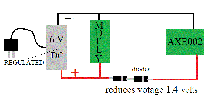
I plan to use one regulated wall transformer for both boards, reducing the voltage to the AXE002 with a simple diode string. Is there a problem with this idea? Thanks!


Take care, Joe.

P.S. Perhaps 3 diodes in the string would be a better choice? J.
 
Last edited:

westaust55

Moderator
Since you are using an AXE002 I presume that you have an 18M2 PICAXE chip.

If you look at the datasheet (link here on Rev Ed / PICAXE website: http://www.picaxe.com/What-is-PICAXE/PICAXE-Chip-Labels/
In section 30 you will see that the ABSOLUTE MAXIMUM allowable voltage is “+6.5V”
In section 30 Table 30-1 you will see that the normal supply voltage can be up to a maximum of 5.5 Volts.

Hence if your 6V wall wart (aka Plug pack) is well regulated ( = stable output voltage from zero to full rated current) then even a single 1N400x series diode will suffice (Vf = 0.7 at 10mA and increases with load current) and two would be an insurance policy. Three should not be needed with a stable 6 V dc supply.

What is the output voltage of the MDFLY busy line when high? PICAXE pins should not be driven more than 0.3 V higher than the supply voltage.
Either include a series resistor (say 4.7kOhm or higher) in the busy line or stay with one voltage dropping diode.
 

joe paul

Senior Member
Hi Westaust55,

Thanks for the information! According to 1968Neil in his post above (2nd from the top), the busy pin voltage of the MDFLY is 5V when high. My wall wart is supposed to be "switching" quality, but I will test it under a load before and after the diode string to be safe. I will be driving some tiny relays with the AXE002, and they are 3 VDC, so I use the diode string trick to use them. So far, my testing has only been with batteries.

Take care, Joe.

P.S. Would there be an issue using 2 separate regulated wall warts, one 6V for the MDFLY and another 4.5V for the AXE002, with both grounds tied together? J.
 
Last edited:

westaust55

Moderator
Two separate supplies with the ground / 0 V lines tied together will work.
Just include the resistor on MDFly to PICAXE signals to accommodate voltage differential as mentions before.
 

joe paul

Senior Member
Hi Westaust55,

Thanks for the info! I will use a resistor to be safe. I didn't know if the voltage regulation circuitry in the 2 different wall warts would play well together. Also, I am leery of hooking up my contraption to my computer for the chip programming, so I will probably use the battery pack for the AXE002 with the MDFLY board unpowered for the downloads.

Take care, Joe.
 
Last edited:

westaust55

Moderator
Thanks for the info! I will use a resistor to be safe.
This is why the standard PICAXE programming download circuit has the 22 kOhm resistor (in addition to the 10 kOhom resistor).

As most folks are aware, the 10 / 22 kOhm resistors are not connected as a potential divider and each has a different function.

The 10 kOhm resistor is used to pull the SERIALIN pin low where there is no program to download.

The 22 kOhm resistors is primarily from the days where PCs used (some still do) the RS-232 serial comms port which by the RS-232 spec can have voltages in the range -25 to +25 Vdc. Many PC’s typically only have the RS-232 voltage swing between -12 and +12 Vdc. These voltages are well in excess of the PICAXE (and native PIC chip) input voltage tolerance. The 22 kOhm resistor in effect drops the voltage at the PICAXE pin (in conjunction with the PICAXE internal diodes) and limits the current into the PICAXE pin.


In your case, the voltage difference between the two chips is only 6 versus 4.5 or 5.5 Volts so the resistor in the line between the two IC’s can be far less than 22 kOhms.
 

joe paul

Senior Member
Hi Folks,

Well, I promised I would update when I got things working. Had the usual bump in the road when 2 audio sockets didn't make a good connection with the speaker jack, so I just spliced into an old audio extension cord. I wasn't getting the left channel; had a problem in the past with these cheap sockets. I used a variation on the code provided by 1968Neil so I could understand what I was doing. Here is what I did so far. It has been a long time since I used BASIC (learned BASIC Plus back in 1977).

Code:
Symbol Baud = T4800           ; Set Baud Rate for Audio Module
Symbol Voice_Out = B.5        ; Set Serial Output pin on 18M2 for Audio Module
Symbol Voice_Wait = pinC.1    ; Set pin 13 as Voice module active (busy Line)


serout Voice_Out, Baud, ($EF) ; STOP MP3 module when initializing power up                  
pause 500

Main:
serout Voice_Out, Baud, ($02)    ; Send command to play file 1 on SD Card

do
if voice_wait = 1 then exit        ; wait until voice module has finished
loop
serout Voice_Out, Baud, ($EF) ; STOP MP3 module            
pause 500

pause 2000
goto Main
I have been going at it steady for about 6 hours, so I will take a break and then refine it. It plays the first file first although I don't call for it, but after I interrupt with a momentary hit on C.1, it works as I expected.

Used a regulated wall power supply like I had inquired about before, but I used 3 diodes (not just 2) to be safe for the Picaxe. Also had one wire break off of the board, couldn't find my old spool of desolder wick, but managed to get the wire back through the hole.

So now I am awaiting my Bluetooth module HC-06 for another round of experiments.

Again, everyone, many, many thanks for all the kind help!

This is sort of connected to my other questions: http://www.picaxeforum.co.uk/showthread.php?27070-Soldering-to-the-AXE002-Board-with-the-18M2-Chip I broke the pin off the Darlington array for pin B.5 for the MDFLY board.

Take care, Joe.

P.S Just to clarify things, I used C.1 as a momentary manual switch, and I am attempting to call the 2nd file although the note says "file 1." I didn't use the "busy" pin. J.
 
Last edited:

joe paul

Senior Member
This code will play the 1st 2 files continuously without being interrupted.
Hope this helps.

Its ok to leave the chip in the socket when soldering it in just be careful not to use too much heat, if you can remove the chip,

Code:
Symbol Baud = T4800           ; Set Baud Rate for Audio Module
Symbol Voice_Out = B.5        ; Set Serial Output pin on 18M2 for Audio Module
Symbol Voice_Wait = pinB.7    ; Set pin 13 as Voice module active (busy Line)


serout Voice_Out, Baud, ($EF) ; STOP MP3 module when initialising power up                  
pause 500
serout Voice_Out, Baud, ($E1) ; Set MP3 volume 
pause 500

Main:
serout Voice_Out, Baud, $01    ; Send command to play file 1 on SD Card

do
if voice_wait = 1 then exit        ; wait until voice module has finished
loop

serout Voice_Out, Baud, $02    ; Send command to play file 1 on SD Card

do
if voice_wait = 1 then exit        ; wait until voice module has finished
loop
Goto main
Hi 1968 Neil,

Your code was a tremendous help. I was having trouble getting my own code to work in the simulator. In my haste, I didn't pay attention to what you said about playing the first 2 files. I will wrap my head around it when I have a chance to digest everything I learned today. The MDFLY board works with the SD card, I did blow anything up, and I got more comfortable with the process of loading a new program on the 18M2 chip.

Take care, Joe.
 
Last edited:

joe paul

Senior Member
Code:
Symbol Baud = T4800           ; Set Baud Rate for Audio Module
Symbol Voice_Out = B.5        ; Set Serial Output pin on 18M2 for Audio Module
Symbol Voice_Wait = pinB.7    ; Set pin 13 as Voice module active (busy Line)


serout Voice_Out, Baud, ($EF) ; STOP MP3 module when initialising power up                  
pause 500
serout Voice_Out, Baud, ($E1) ; Set MP3 volume 
pause 500

Main:
serout Voice_Out, Baud, $01    ; Send command to play file 1 on SD Card

do
if voice_wait = 1 then exit        ; wait until voice module has finished
loop

serout Voice_Out, Baud, $02    ; Send command to play file 1 on SD Card

do
if voice_wait = 1 then exit        ; wait until voice module has finished
loop
Goto main
Hi 1968 Neil,

Thanks again for the code. I have a couple questions:

What does the "T" mean as the prefix do for the baud rate? (T4800 vs. 4800)

Where can I find the parameters for volume control? You used "E1" but I don't have any volume parameters with my board's info.

Thanks!

Take care, Joe.

P.S. Feb-6-15, I found the information about the baud rate; understand it a little better now. I think I understand something about setting the pin "high" first. J.
 
Last edited:
Top