A confused teacher.

reynoldsw87

New Member
Afternoon all.

I have just switched from Genie to Picaxe. I am trying to develop a new project for a year 8 class using an 08M2 chip.

I wanted to have a dedicated download board to program then chip and then a seperate board for the chip to go on in the project.

I am finding conflicting information about what to do with the serial in pin on the board to go in the project (with no download socket).

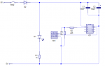
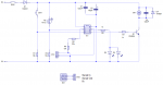
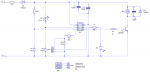
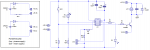
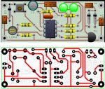
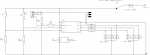
Attached is a circuit diagram. Please could individuals help me out. Capture.PNG

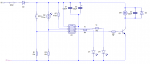
Thank you in advance.
 

reynoldsw87

New Member
Sorry just remembered another question.

On the download board, do i need to tie the floating pins at all? High or Low with a 10k?

download.PNG
 

Goeytex

Senior Member
On the project board, Resistor R7 needs to tie to 0V , not +V. I would recommend a value of 10K to 47K. 470K is probably too high. I prefer a 10K.

It is not generally necessary to tie unused inputs to 0v or +V. However it is considered good practice not to have floating pins..

To prevent pins from floating, 08M2 has internal pullup resistors that can be activated via the "pullup" command in Picaxe Basic. Another option to prevent an unused pin from floating is to make it an output, assuming the pin is not "input only". This can be done with either a high or low command. Otherwise a 10K resistor to either +V or 0V will keep the pin from floating.
 
Last edited:

hippy

Technical Support
Staff member
We would recommend including the download interface on all PICAXE boards. There is minimal cost to be saved from not including it and a PCB can be designed to include the full download interface even if the jack socket is not initially fitted to save costs.

Fitting the download socket saves having to remove the PICAXE from the board whenever it needs reprogramming, limits the potential for damage to the chip legs and risk of incorrect installation, and also provides a means to debug the hardware and the program when running within the PICAXE.

If the download interface is not included then the Download Serial In pin should preferably pulled to 0V with a 10K or 22K resistor.
 

AllyCat

Senior Member
Hi,

Yes, R7 MUST go to ground not Vdd, and I agree with all that Goeytex has said.

But I do encourage you to put a "programming" socket also onto the Project board. It only requires one extra resistor and the (very cheap) socket (or even just 3 pins if space is tight). One of the real strengths of PICaxe is that the Programming Interface can be used also as a major debugging and diagnostics tool.

Cheers, Alan.

EDIT: Ah, beaten by hippy again.
 

neiltechspec

Senior Member
My thoughts

As everybody else has said, serial in must be tied to 0v, and it is worth adding both resistors (10k + 22k).

Not actually necessary to put a download 'socket' on the board, I always use a 3 pin header instead (really cheap),
then use a short (6" in my case) 3 pin header socket to 3.5mm jack socket lead.

Neil
 

tmfkam

Senior Member
Not actually necessary to put a download 'socket' on the board, I always use a 3 pin header instead (really cheap),
then use a short (6" in my case) 3 pin header socket to 3.5mm jack socket lead.

Neil
Me too. And label the pins so I know which way round to connect it. Why isn't it working? Ah, oops!
 

manuka

Senior Member
reynoldsw87: Dedicated download boards are just asking for trouble with youngsters- I also strongly advise you NOT to go this way! IC swap outs mean pins WILL get broken & bent and the DIP chips dropped,squashed or mixed up. Very useful productivity benefits arise with incremental program tweaking of course anyway. This is a PICAXE strength = "One board to rule them all".

I must have been involved educationally with 1000s of PICAXE circuits over the last decade, and ALWAYS include an onboard programming point. Many of these setups are breadboard based - electronic soldering is a craft best mastered in its own right of course!

Check fellow Kiwi Andrew Hornblow's kid friendly 08M2 approaches => https://picasaweb.google.com/picaxe

Stan
 

Morganl

Senior Member
I am thinking of making a programming cable using an IC clip like this:
http://www.ebay.com/itm/1PC-OF-IC-TEST-CLIPS-ITC-8A-8PIN-MADE-IN-TAIWAN-/181366600829
Then the only programming interface needed on the target is a resistor.
(rest is between the clip and connector for AXE027 cable)

If i have that resistor *also* in the test clip, plus supply power to it and have a decoupling cap, then it can *also* program a loose PICAXE.
No programming board needed in either case, just the target or notning else than my clip mojo.

Same 8 pin clip fits 08M2, 14M2, 20M2, 20X2. Paint the side to go with pin1.
 
Last edited:

reynoldsw87

New Member
Thank you all for you quick responses. Sorry about not getting back to you all quicker, I currently have no internet at home.

I was originally leaving the download socket out because I have a very limited space on the board but have added one in now. I am going to use 3 pin set up (thank you neiltechspec) and then have a download socket on a separate board with 3 pins for students to plug it in to.

I have attached the circuit diagram with the updated components. Could someone check over it?


manuka: thank you for the website link. Would it be possible to pick your brains some time on potential school projects. Electronic projects seem to still consist of a fuse tester in English schools!!

VibroV2.PNG

As you can also see from the PCB layout, the space is tight(ish). the main PICAXE board will have PCB pins coming down from it and will stack on top of the battery board, like the shields. There is a reason behind this that I will not bore you all with it.

VibroV3.PNG

Thank you all for your help.

Will
 

neiltechspec

Senior Member
You have a slight error on the 22k / 10k serial in resistors.

serial in pin - 22k - CN1 - 10k to 0v.

The junction of the 22k & 10k should go to the programming pin, if you get my drift.

edit: I would use 100k for R3 also make R6 & R7 330R's.

Neil.
 
Last edited:

grim_reaper

Senior Member
Electronic projects seem to still consist of a fuse tester in English schools!!
I don't know what's happened to the curriculum since I left school, but when I did my GCSE in Design Technology (nearly 20 years ago now - eeek!) I distinctly remember making a lot of PCBs, LEDs, NAND gates and all sorts! No microcontrollers though, to be fair.

A quick glance at your circuit diagram and I think there's still some issues with it. I assume the +ve connection to C2 being missing is just a typo (clicko?).
Your orientation of the CN1/CN2 connectors seems to wrong - one of them is the wrong way up; assuming that the square pin indicates Pin 1. Just flipping CN1 vertically should do the trick with that.
More importantly, the resistor arrangement is incorrect for the serial in pin. The 'PR' pin needs to go to the junction between R4 and R5. R5 goes off the PICAXE to prevent it from spurious current and R4 goes down to ground to tie it low when the programmer is disconnected.

I hope that helps. Carry on educating those children!

Beaten to the reply again!
 
Last edited:

AllyCat

Senior Member
Hi,

It's generally not a good idea to connect two LEDs in parallel with a single current-limiting resistor, particularly if they are different colours (different forward voltages), and why are there two anyway? With a 5+ volt supply they might be better connected in series (depending on colour), but two separate resistors would give more flexibility (control of brightness/balance).

Presumably the power supply is 2 x Lithium "Coin" cells in series? Have you checked their maximum voltage, it might be a little high for a PICaxe, even with a series diode? And the rechargeable versions are 3.7 volts, which can exceed 4 volts each when initially taken off-charge. Also what type of motor are they expected to drive?

Cheers, Alan.
 

reynoldsw87

New Member
I am so glad I have till September to learn about PICAXE properly. The conversion from GENIE was not as simple as I expected.

Noticed the mistake with the Download socked after I posted the thread, I have been teaching so was not able to change it.

grim_reaper: the new national curriculum for electronics, computer science and systems and control is all microelectronic based etc. We just need the exam boards to catch up now and move away from the dreaded 555 timers etc. Technology has changed yet they have not. The way circuit wizard rotates object it will not allow me to rotate CN1 and CN2 to the correct orientation..... annoying....... hence moving to design spark pcb next year.

AllyCat: They are minature LEDs (3mm) but after thinking about it, I am going to reduce it to 1 LED. The board will be powering this motor. (http://www.kitronik.co.uk/2541-minature-3v-vibrating-motor.html)

The project is based on this: http://www.kitronik.co.uk/c2150-vibrobug-kit.html
At the moment it is a simple circuit and I would like to make a double stack board that will fit underneath the current product and allow an element of programming to develop from the PICAXE mood light we do in Year 7.

Hope I have addressed everything.

VibroV5A.PNGVibroV4A.PNG
 
Last edited:

srnet

Senior Member
Quite a few of the PCBs I have done are tight on space.

The program connection need only be 3 small pads with added wire loops. Then to the connections in 3.5mm stereo line socket fit 3 wires with test clips on the end. When you want to program plug in the PICAXE program lead to the line socket attach the test clips to the loops.

So if you have the space for just 3 small pads, you can fit a program connection.
 

MartinM57

Moderator
There's plenty of room on the "main" PCB for the download socket - move stuff around a bit :)

There's lots of components with no annotations so it's hard to check if the PCB matches the schematic - as C2 still doesn't have a connection to Vcc I presume your design tool /can't compare the schematic with the PCB to make sure they are the same?

Are they double sided boards? The reversed component annotations seem to point to this, but there's only one (red) set of tracks?

The "battery" board has no schematic at all it seems - what are the two components on it, the batteries overlap each other so won't fit on the board easily? What sort of batteries are they? CR2032 coin cells will go flat - then what?...ditch the board or unsolder/resolder? Also CR2032 are low capacity and might not last long and don't take kindly to being short circuited - which is easy to do when they are PCB mounted and the kids are putting the PCBs down on metal surfaces etc
 

AllyCat

Senior Member
Hi,

Hmm, an interesting idea, but I (also) have some concerns about the batteries (and lack of full interconnection details). You originally mentioned a "6 volts" supply, so I assumed the two cells are in series, but that is NOT the way to go. The motor is rated to only 3.6 volts and requires a nominal cuurent of 75mA at 3 volts. However, I've no idea how much current you can actually get out of a CR2032 since the data sheet only specifies a nominal current of 0.2 mA, with no indication of its source (internal) resistance.

Personally, I would either put the cells in parallel, with a resistor in the supply line to the PICaxe decoupling capactors (to prevent transient "brown-outs" when the motor starts), or (probably better) use individual cells for the PICaxe and motor. A PICaxe can happlily work down to 2.5, volts so at least with separate cells you'll only have one battery that has to be replaced every couple of hours of use. :)

Cheers, Alan.
 

reynoldsw87

New Member
MartinM57: I know there is quite a bit of space but I am trying not to put the components too close together as the students will have only soldered 2 or 3 times before starting this board. The battery holders in real life are smaller than the ones depicted in CW hence them overlapping slightly. I have laser cut the design on to cardboard and all components can fit in without overlapping.

AllyCat: I will draw up some proper circuit diagrams that break each section down and make it clearer for all. I will try the single battery for each component approach. Its strange I used a protoboard and it all worked out but coming on here has shown me that maybe I should have gone back to the proto -board for some more testing.

I will get on with the design changes now!!
 

reynoldsw87

New Member
Ok,

Changes made. No doubt there are mistakes!! I am questioning everything I do now as I feel I am back in the students shoes not knowing anything.

Question: Do I need a switch on the MOTOR power supply, if so can I use the one I have and double it up? Please excuse the poor circuit diagram, I was unsure how to present it. As Im sure you can all tell I am new to this!!

VibroV6.PNG VibroV7.PNG
 

Hemi345

Senior Member
This might sound like nit-picking, but I would wire the programming header like it is in the Manual 1, page 44. Putting Serial-In on the middle pin. This way your programming header matches the manual if your students should get so curious as to consult it AND if the connector is accidentally reversed, the potential of +12V will always go to the SI pin rather than the ground pin.

Also, shouldn't -VE(D) and -VE(B) be connected together/common?
 

MartinM57

Moderator
I'd definitely put SW1 in the +ve line before or after D1 - it hurts my head to switch the -ve line of the PIACXE battery when the PICAXE and motor batteries are connected (which you need to do as Hemi says). You might also get some strange circuit effects by having the PICAXE +ve'ly powered all the time. Keep it simple/normal - switch the +ve line like every one else does...

Have you tried a CR2032 -> 1N4001 -> motor -> a switched on 2n3904 -> Gnd.. does the motor work and how long does it run for before the CR2032 goes flat/can't supply enough current? I wouldn't even dream of making a CR2032 deliver 75mA - they're predominantly designed for RTC/BIOS backup batteries, little clocks with LCD displays/digital calipers etc.
 

manuka

Senior Member
reynoldsw87 By all means contact me 1:1 - start with a PM (private message) & I'll give my most suitable email.

Your UK Year 8 students (assumed 12-13 yo.) will probably be very weak on e-basics, so IMNSHO perhaps assume nothing & start simply - VERY simply! Most at this age have never heard of Ohm's Law, used a DMM,had IC pinouts explained, decoded resistors or even stripped a wire.

Kids love the hot metal associated with soldering of course, but many initially just "fool around" -naturally this is all part of learning about ones tools & materials & associated skills. In my lengthy experiences (as a pre teen learner myself & later in technical education & the military) it takes MANY HOURS & MUCH PRACTISE to get most newbies up to even modest electronic level soldering.

As a career educator I -sigh- also ask the usual boring questions that tend to blight school based learning - delivery time, resources, class sizes, facilities, budgets, admin. & peer support, gear storage, classroom management ease, culture/motivation of the kids, your workload, duty spells, MARKING, topic assessment, take home projects,pastoral care, parental issues etc etc etc. Any one of these factors may seriously skew teacher enthusiasm!

FWIW I found the boxed setup below both cost effective & very mid teen student friendly. Kids got to make them as part of the course & were assessed for neatness etc. They then could take them home (both during the course & for keeps), but sourcing cheap USB-D9 cables however was of course needed too.

Cheap & very low current drain "solar motors" can readily be driven by this setup (via an NPN).

Regards- Stan. (survivor of 40 years at the chalkface-mostly tertiary)
 

Attachments

Last edited:

g6ejd

Senior Member
The cell internal resistance is (according to Texas Instruments) typically 15R and they recommend a maximum current demand of 30mA. Typical capacity is 100mA-Hr.

Your design will work, but the motor is rated at 75mA in normal use, so that twice the recommended demand from the cells, I think you will be disappointed with durability or will need to keep changing batteries for new ones. I believe your design needs to be made pragmatic by increasing the cell capacity, or bringing out the motor supply to a separate feed point, so the PICAXE can run off the CR cells and the motor from an another power source. Mobile phone batteries have far more capacity than the CR2032 cells. Like others have said, I would not even dream of using a CR2032 cell for this design. If your aim is to make something small and practicality is not an issue, then the design is good, but I wonder how students will perceive a design that has limited useful life.
 

AllyCat

Senior Member
Hi,

Yes, the battery earths (neg) need to be linked and I would put the on/off switch only in the PICaxe supply rail; the transistor can act as the switch for the motor circuit. But to be absolutely certain (e.g. for long "shelf-life" at high temperatures) then put a resistor of say 10k across the base-emitter (to prevent any small leakage current into the base being amplified).

No, I wouldn't attempt to use a coin cell to drive even that tiny motor either. But we have the quandary that it's based on a "published" and marketed design, so presumably it can be made to work (sometimes/usually?). However, it may require a particular brand (quality) of cell, and in practice the cell's impedance might be such that its terminal voltage falls to (say) 1.5V at 40 mA, which could still run the motor, but not a PICaxe. That would vindicate the decision to adopt separate cells for the motor and PICaxe.

Do the diodes in series with the cells have a specific purpose? Of course they protect against reversed battery connections (as such, they would be better placed on the main board) but a forward voltage drop of around 600 mV is quite a lot to lose in a 3 volt circuit (putting an 08M2 very close to its lower limit). Schottky diodes could be used, however, it's more normal practice to employ "mechanical" protection (e.g. the cell cannot be inserted incorrectly, or the contacts do not touch the cell if it is) but I don't know about the holders that you are planning to use.

Finally, I hope that this is all usefully "constructive criticism". IMHO much of the design is already "right": The light level can be detected by either digital (simple on/off) or analogue ("intelligent") commands and the "input only" pin cannot be accidentally set as an output (which might create havok if the button is then pressed). Potentially, the motor speed can be controlled by PWM and you've used all the normal recommended decoupling and protection components. ;)

Cheers, Alan.
 

manuka

Senior Member
FWIW my experiences show CR2032 Lithium cell powering should be avoided in e-classrooms with early teens .

No only are the cells often costly (& elusive when needed) & prone to rolling away if dropped, BUT rascals will get up to mischief with them. At the least they'll see if the cells go bang in a fire or drilled, but more alarmingly CR2032 lend themselves to insertion in coin vending machines or slight of hands tricks with real money. Some countries coins are almost exactly the same size!

Alkaline AAs are currently the most cost effective "bang for buck" energising source (that's if you've project space for them), and their capacity is far greater than coin cells. 2 or 3 x AA (3 - 4.5V) will power most PICAXE circuits and small motors for ages, & real skinflints can use 4 x weary AA to get the last Joule out of them. Switched AA battery boxes are cheap too, & great for both holding the cells and also the project PCB. Such lateral thinking aligns with the present crazy stage in electronics when boring but essential project "finish" can cost more than the hitech electronics within.

Footnote: For those dear souls unfamiliar with laughable schools budgets I add that ongoing battery costs (especially 9V types) often nickel & dime tech departments to death... Here in NZ I once helped a school that rotated their 200 Y8 students thru' a 20 hour e-course (~25 students per class), with TOTAL budget ~$3 (under 2 pounds) per head for EVERYTHING. This included take home projects! Only my own extensive resources & solar garden lamp hacking were able to save the day...
 

Attachments

Last edited:

walton1666

New Member
This is my first attempt at a post so please be sympathetic if I get it all wrong.
As an ex-electronics teacher I am most jealous of your position I really miss being in the classroom.
The advice on the forum is excellent but may I add my feelings.
I have produced a PCB layout for your project which may have faults but hopefully will help with your designing.
(I hope it’s attached.)
I would use thicker tracks and larger pads if I was building it.
I have put pin2 in the middle of the programming header as suggested by hemi345.
The diodes from the battery board are now in the top board to eliminate the chance of the leads getting crossed.
Schottky diodes would be best as recommended by AllyCat and in my experience diodes are needed to protect the 08.
I've had a nasty burn from an 08 with the power the wrong way round it’s amazing what pupils can do.
I’ve put a second LED on pin 7 (some say this needs a jumper so it can be disconnected but it’s always worked for me).
I assume the board is 2.5 x 1 inch.
As for the separate power supply I’ve joined the 0V rails as suggested on the forum.
Personally I would use the same AA cells for both motor and 08.
3 x 100nF on the motor terminals help. (1 across the terminals & one from each terminal to the case.)
I’ve never used CR2032 Lithium cells in the class room and suspect AA’s are cheaper (15p for holders [100 off] from Rapid) but obviously larger and heavier.
When it doesn’t work and many, in my experience, don’t first time (maybe I was just a rubbish teacher.) deciding if the fault was software or hardware was difficult, so I recommend building a tester to plug into the 8 pin socket before handing out the 08’s..
Red and green LED’s across pins 1 and 8 red lights if power wrong way round green if OK.
LED on pin 3 and transistor driven LED on pin 4.
Switches to pins 5,6,7 to test motor and LED’s.
I’ve also put an op amp on pin 2 to check the 10k & 22k resistors are the correct way round (the 22k isn’t to 0V).
I’m sure testing with a multi-meter would be better but difficult for the average 12 year old in the time available (even if you have the meters).
I wish you all the best I’m sure you’re in for an exciting but exhausting time.
 

Attachments

MartinM57

Moderator
Good point about the diodes - on my CR2032 PCB mount battery holders, putting the battery in upside down leaves the -ve side unconnected, so no harm done and no diodes would be needed

(..and it shorts the two battery holder connectors together - good or bad news depending on what you are doing with the battery)
 

grim_reaper

Senior Member
I have produced a PCB layout for your project which may have faults but hopefully will help with your designing.
Slightly OT; that PCB design software looks really good - emphasis on the 'looks', I love the pictorial layout. What software package is it?
I get the feeling I've spent too long building 'pretty' software and not enough time on real code!
 

reynoldsw87

New Member
Thank you all for the information!!

I have a free now and then lunch so I am going to read through what everyone has posted and have a look at the design. I have just hooked up the battery, motor and multimeter to test it. As we speak it has been running for 15 minutes solid but it is now down to 1.70 volts so may not last much longer.

I was originally going for a smaller project to reduce cost on the size of acrylic that we will have to use. Luckily the product design teacher will cover the cost of the acrylic and some of the electronics. I am not against using AA or AAA batteries, I will just have to make the project bigger and change the motor that we use to accommodate the extra size and weight.

grim_reaper The software I am using is Circuit Wizard 1.5 (very old now). Afraid I don't know what walton1666 is using but would be interested to know.

I have recently got Design Spark installed on the school computers due to it being free and students would be able to download it at home when they take systems & control at GCSE. Anyone else got any recommendations of software that can be used for free in school? (Yes once again the dwindling budget wins the argument!!)

I have only been teaching 6 months and already im letting budgets rules my life, which then dictates the project and then usually the quality. The government want a set of students that are able to program but aren't willing to provide the funding................ but that is another discussion and I don't want to be one of those teachers that gets on their high horses!! I teach because I love teaching and I want others to enjoy systems and control as much as I do!
 

manuka

Senior Member
running for 15 minutes solid but it is now down to 1.70 volts so may not last much longer
This surely wraps up the pondering - lithium coin cells are NOT suitable for your motorised projects!
PICAXEs will of course cease operating at ~2.5V anyway.

As an educator you also have a "greenie" responsibility to show you are using resources appropriately. Bulk purchase of CR2032 Lithiums may initially make individual cells cheap enough,BUT students won't have such luxury when replacing them.

Dead cells will soon abound too,& bright sparks may Google for imaginative "dead cat" applications...

I have only been teaching 6 months
Good man- I admire your enthusiasm! FWIW (& recalling my own early days in the calling), it may be best to curb your energies & just base the topic around kits already available. In fact I've had workmates in the past who point blank refuse to teach a course unless every last resource & teaching aid is supplied by admin. Although this is not the way I've ever thought, it's perhaps fair enough - they're employed & trained to teach,not make & maintain the equipment.

Settling into the culture & demands of the school usually takes new teachers a good 2 years. Lesson prep., marking, classroom teaching & near ENDLESS associated duties demand such initial ENERGY that you'll threaten STRESS, EXHAUSTION & neglect of other life activities . Back in my early years I well recall regularly still repairing/making & scrounging science & tech. gear late on Friday afts/eves (& often weekends) when mere "chalk & talk" teachers had long since repaired to the local pub!

It's worth reflecting too that although most ~12 yo Western city kids are smart phone & games gurus, many are now VERY unfamiliar with classic hand tools. Soldering iron safety & technique alone may need significant careful instruction & practise- even here in NZ I've sometimes had to show kids of this age how-to-use-a-screwdriver!

EXTRA: To avoid the sorts of tangential replies that -sigh- often characterise this Forum, best you respond to the boring queries I (& others) asked back at post #23 etc. Assumptions may otherwise be made until "Argh- if only you'd told us earlier" clarification is given. Where in Britain are you? What school size? Mixed gender? State or private?

Please also supply or link us to the syllabus/ assessment scheme/ lesson plan /work outline that you are required to instruct to as well. This is what the system is expecting you to follow of course!

Stan.
 

reynoldsw87

New Member
Sorry about the delayed response, I dont have internet at home at the moment and living in a tiny village in the country side means that I have no mobile signal to get online.

Thank you all for your advice. I have taken it all on board and decided to make the overall product bigger and use AAA or AA batteries and increase the size of the motor (with a home made off centred cam on it).

I am in the process of coming up with couple of designs to see if it will work. The feedback that I have received has been invaluable.

Stan I am based in Shrewsbury, Shropshire. The school has around 750 pupils from year 7 to year 11 (11 - 16yo). It is a mixed gender school, where Technology is compulsory throughout the school. We rotate between all areas of Technology over the year thus resulting the students have 5 weeks in each area (systems, graphics, food, res mat, textiles, product design) from year 7 - 9. In Year 10 students then opt to take one Technology at GCSE. The 5 week rotations equates to 13-14 hours, depending on which week the students start. It is an outstanding state school.

I currently do not have a scheme of work for the project. I am trying to get ahead of the game and get projects started and tested before I introduce them in September. I will have the summer holidays to write the schemes of work once I know what the projects area. I have a rough idea of what I want to teach/cover and feel the projects I am doing will cover that.

I will post an update in the next couple of days of the PCB design. I am currently proto-boarding the new circuit diagram.

Thanks all.

Will
 

lbenson

Senior Member
>use AAA or AA batteries

Note that AAA batteries suffer from much the same lack of useable charge relative to cost as coin cells. They are certainly useful when size overrides all, but AAs will give more "bang for the buck", not to mention the advantages of running a picaxe from 2 AAs in a 4-AA switched box, as Stan mentions.
 

geoff07

Senior Member
I must support the point about building in the download circuit. I work with GCSE DT kids who are using Genie with separate download boards, and the number of reversed chips and broken pins and time spent sorting it is much more than would be with the built-in circuit, not to mention delayed turnround and thus slower development.

I would be interested to know what pcb design software you were using with Picaxe. The genie app in my view leaves something to be desired (putting it mildly) for pcb layout and routing, though is quite good for limited schematic design and simulation.
 

manuka

Senior Member
Will: In brief - Ok & thanks for insights! 5 weeks totalling 13-14 hours is VERY tight, especially for youngsters... Are things intended as "take home" ? I repeat that most kids at this tender age usually have little experience with even a simple DMM, soldering iron, electrical terms, hand tools or basic components. The need to upskill learners into e-tech culture is a major reason why "Electronic projects seem to still consist of a fuse tester in English schools" remains the norm in short courses!!

increase the size of the motor (with a home made off centred cam on it).
Why not just use cheap "pager motors" -classic ones are very educational, although the modern pancake types are more elegant. Your preteens would absolutely love making racing bristlebots of course I'd say! See =>https://www.youtube.com/watch?v=O-25ZrXOoaQ Stan.
 

Hemi345

Senior Member
OT: What is going on with this thread? I see there is a new post in it so I go to view it and Manuka's is always the last post (I read that about the bristlebots yesterday morning!) but there are new posts above it that I haven't read before. :confused::confused:
 

manuka

Senior Member
Guilty as charged. At one stage I'd deleted my initial posting while pondering bristlebots.You probably hence caught things while I was in pre morning coffee limbo!

Eccentric Rotating Mass (ERM) vibration "pager motors" are nifty devices, & bulk sell on e-bay etc for only a US$ or so each. Their offset weight can usually be eased off the shaft if you want a normal motor. Most draw ~70-100mA at 3V, but I've run across some that still work OK at half that, & hence suit cheap alkaline AA cell powering.

You don't need to use toothbrushes of course -stiff wires etc work well too. A benefit of this is that students also gain hands on experience with hand tools,wires & components. Although hard to credit for us old timers, many of today's city kids youngsters have never seen the insides of covered wires. Most are often amazed to be shown gleaming metallic copper under the insulation! Stan.
 

Attachments

erco

Senior Member
"Electronic projects seem to still consist of a fuse tester in English schools" remains the norm in short courses!!
Love all your stuff, Stan!

Very OT, but since you brought up English and Electronics, this yank has to ask a question. On this side of the pond, Lucas (auto electrics) has a humorous reputation as "the Prince of Darkness", as many of my vintage British sports car-loving friends will attest. Does that same sentiment prevail in the UK, or is it just an American (mis)conception? There's a funny read at http://www.bigmacktrucks.com/index.php?/gallery/sizes/7590-lucas-prince-of-darkness/large/
 

reynoldsw87

New Member
View attachment Mood_Light_Proto_DRAFT_CD_V1.pdfEvening All,

Thank you very much for all your help with the last project. I have made a few versions to the board and will get photos once the toy/kit is complete.

So now it is time for the next project. Very simplistic and I expect a large majority of you are fed up of answers questions on a mood light.

PWR: 6V, 4 AAA or AA
Input: LDR and PTM Switch [Students will be able to choice which one they want]
Output: RGB LED(https://www.sparkfun.com/datasheets/Components/YSL-R596CR3G4B5C-C10.pdf)

QUESTIONS:
What value resistors would you recommend to use if 1) 1 LED used? 2) 2 LEDs used? 3) 3 LEDs used?
From experience do others think that 3 leds would require a transistor?
If the student decides to only use a single input, will the other input pin have to be pulled to ground and not left floating? Would this be the same for the output pins?

I am trying to make a board where the students can have the option to "customise" it depending on the project.
Mood_Light_Proto_DRAFT_CD_V1.PNG
 

g6ejd

Senior Member
Circuit design looks OK. Red LED pin-1 requires a 220R the Green and Blue require 150R as the forward voltages are different, I assumed 15mA. e.g. (5 - 1.8)/0.015= ~220R for R8 you could increase the values by 50% to lower the source current from the PICAXE. No need for transistors. Inputs have an internal pull-up
 
Top