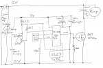
I am developing a solar thermal (hot water) system with a control system using the PICAXE 20X2 chip. I’ve done plenty of user trials and now I’m gearing up to commercialise.
To get my CE marking I believe the system needs to pass some EMC tests – so that we know it won’t be upset by other systems in a house and it does not in turn produce undue interference, eg to radios etc.
A test lab recommends initial testing on Radiated Emissions, Common mode RF immunity and Fast Transient Immunity, as a quick “check on design strategy”. This will cost and I don’t want to have too many iterations before getting a compliant circuit.
I’ve not found any thread on this kind of issue.
So my questions:
Has anyone experience of getting a product using a PICAXE controller to market?
Are there tests you know that will identify problems in the areas above?
Are there any datasheets I can send to the lab?
Are there any known issues with PICAXE circuits which I can address first? In particular I am using hpwm which might produce a noisy signal when its amplified with a FET to power a 12V pump motor. I also use the DS18B20 temperature sensors.
Any help, leads, links, guidance, etc will be very welcome.
")