These first posts are a guide to the making of the controller. If you want to make one yourself, remember to read the entire thread before starting construction and no liability is accepted if you break your own computer.
[SIZE=+1]Preparation[/SIZE]
Tools required:
Note: A 4-pin power plug and 5V/12V power supply is recommended for initial testing before moving this to the computer.
My design uses the front panel headphone connector for programming the PICAXE as I never use it. However, everything in a PC shares one ground so the front panel PCB which has USB ports on it too has one big ground plane. Because PICAXE uses the sleeve connection on the 3.5mm cable as Serial Out and not Ground, this ground plane has to be separated in order to enable programming of the PICAXE.This can be done using a grinding disc from the rotary tool set.

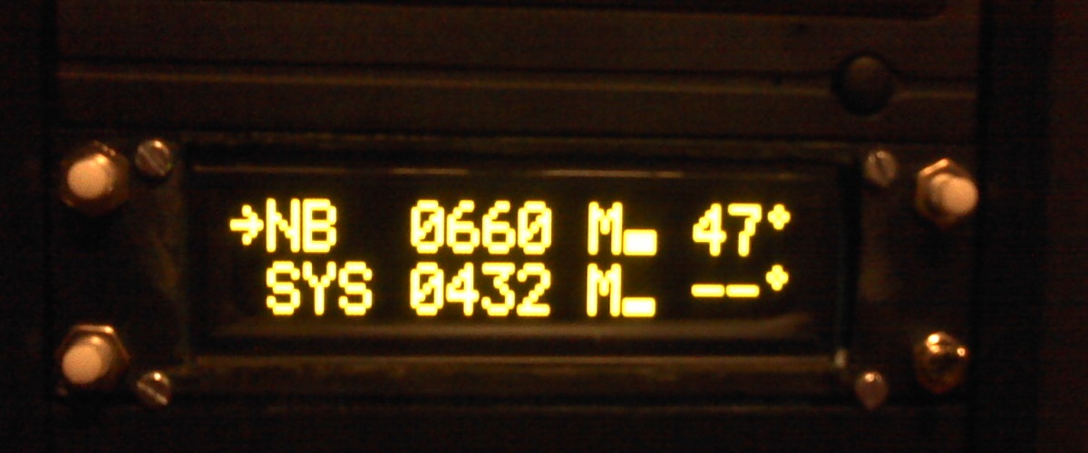
You will need to install thermistors where you want to monitor the temperature. I've only got one thermistor, which is the Techsupplies one. You will need to solder some long wire to this thermistor and insulate these connections with electrical tape. You will also need to apply thermal transfer tape to the thermistor and then you need to shove the thermistor as far as possible into the northbridge heatsink and try to position it so that the fan isn't directly cooling this thermistor! On the other end of the wire, solder a two pin 0.1" socket.


Continues in next post due to four images a post limit...
[SIZE=+1]Preparation[/SIZE]
Tools required:
- Rotary tool with cutter/grinder and drill bits such as Maplin's N29HH
- High current supply for tool above since the power supply included is rubbish and prohibits the tool from operating at its maximum capability (I used a lead acid battery)
- Stripboard cutter
- Soldering iron (with solder)
- Flatblade screwdriver
- PICAXE programming cable
- Computer to mod and program PICAXE with - both can be done with the same computer as long as it won't overheat when both fans are stopped during programming
- Some stripboard - I used 46 rows of strips 24 holes long
- PICAXE-28X2
- 4-pin molex power socket
- IC socket for PICAXE
- A few 0.1" pin headers and sockets
- Two 1A fuses to protect computer in case of failure
- Two 100µF electrolytic capacitors
- Two bulk capacitors of any sensible value - I used 47µF
- Decoupling capacitor
- Resistors
- 16MHz Resonator
- Two low power NPN transistors
- Two high power PNP transistors - cheap low quality ones may also need small heatsinks
- Wire and jumper links
- Two thermistors
- Three push-to-make switches for panel mounting
- SPDT break before make toggle switch (but you can use a SPST with pull-down resistor instead)
- Blank front panel for your computer case - you'll have an additional one spare for each other 5.25" device installed
- Set of four M3 nuts and bolts
- Large character 16x2 OLED (Rapid 57-2296) or LCD (Rapid 500161)
- Two case fans preferably with tachometer signal (required for speed reading)
- Thermal transfer tape
- Insulation (electrical) tape
Note: A 4-pin power plug and 5V/12V power supply is recommended for initial testing before moving this to the computer.
My design uses the front panel headphone connector for programming the PICAXE as I never use it. However, everything in a PC shares one ground so the front panel PCB which has USB ports on it too has one big ground plane. Because PICAXE uses the sleeve connection on the 3.5mm cable as Serial Out and not Ground, this ground plane has to be separated in order to enable programming of the PICAXE.This can be done using a grinding disc from the rotary tool set.

You will need to install thermistors where you want to monitor the temperature. I've only got one thermistor, which is the Techsupplies one. You will need to solder some long wire to this thermistor and insulate these connections with electrical tape. You will also need to apply thermal transfer tape to the thermistor and then you need to shove the thermistor as far as possible into the northbridge heatsink and try to position it so that the fan isn't directly cooling this thermistor! On the other end of the wire, solder a two pin 0.1" socket.


Continues in next post due to four images a post limit...