ADC , electric input pulse counter, help please

Buzby

Senior Member
Yes, fully agree. Much better to time the duration.

But JPU is just beginning, so I started with a simple 'count over 5 seconds'.

Once he's got this working we can move onto duration timing.

I'd much rather stay with analogue than drive the input to digital levels.

With analogue JPU could move on to measuring the noise margin, or waveform slope, or look for irregularities, or plot traces.

There is so much more to be derived from an analogue signal.
 

JPU

Senior Member
Thanks Buzby and Borris for taking the time to help with this. It took me several reads of your post, Borris, to understand what you meant. Once I was able to grasp what you said it makes good sense and it looks like a way to go. I think Buzby is on the right track with sticking with the ADC value as that makes perfect sense regarding the ability to further analyze or even filter the signal.

I have enough to get on with now for the next couple of days so I will use your code Buzby to get things going and then maybe attempt to produce something along the lines of Borris`s idea. FYI: the scope is nice, but I haven't a clue what it can do in all and I'm still very new to scopes!

Thanks again guys and I will get back to you once I have made some progress with your suggestions!

Cheers

Justin
 

boriz

Senior Member
He said he only wants BPM. I'm just taking him at his word. And it doesn't get much simpler (or more accurate) than PULSIN.
 

hippy

Technical Support
Staff member
The biggest problem with counting infrequent events over a short period of time is inaccuracy; anything between 60 BPM and 71 BPM will register as 60 BPM using a 5 second sample period. That's about +/-10% accuracy. It's usually better to measure the time between two events then extrapolate the rate from that.
 

JPU

Senior Member
Hi Guys

Well, I have had some fun. I put Buzby`s code to the test and got some interesting results. The most noticeable problem was the inconsistency in the BPM. I think this was due to the 5sec time limit. Its not really long enough to get a good result as it depends so much on when the pulse ends. When you think about it, this is obvious. eg 5 secs could be 5, 6 or 7 beats multiply by 12 and you have 60, 72 or 84 yet the heart can easily vary this much over 5 secs. So a massive learning curve for me there and I can see why you all pointed to the measurement between pulses!!!

So I used Buzby`s code and incorporated Boriz`s idea. The results are ok, but yet again all over the place????? So I used the second probe on my scope(Its the first time!) to try and see what was going on. My first thought was that it might be the debug command causing a delay in the program, but its not. I have altered the code and I still get the same problem. I have included a pic. The blue trace shows the heart beat, in theory the yellow trace should be high in the area between the peaks, however as you can see it seams to start half way through or when the value of the yellow trace goes negative???

I am lost. Its probably a simple glitch in the program code, but until I figure it out I cant really proceed with my testing.

If you guys can help I'd be grateful. Also I know this isn't as simple a question to answer, but the actual loop time is 3.44 ms ,,,how can I use this figure instead of 3ms which I have used just to test??

Regards

Justin

Code:
#picaxe 08M2

' Hearbeat


' Symbols
Symbol PulseLED 	= 1

Symbol ADCval 	= b5
Symbol TrigLev 	= b6
Symbol PulseCount = b7
Symbol BPM        = b8
symbol timecount  = b9

' Code starts here

TrigLev = 100


' Main loop, repeats indefinately
do
low 2   'set toggle output to off
     
     
	do
	
	
		do	' Stay in this loop until trigger level reached
		
			toggle 2    		'toggle output to scope  on
			timecount=timecount+1   'count loops in of this loop
			readadc c.4,ADCval 	'read adc on c.4
			
		
		loop until ADCval => TrigLev	'loop until trigger level 100 reached
		
		 low 2				'switch output 2
		High PulseLED			'switch on pulseled to indicate beat
		pulsecount=timecount*3		'multiply no ofloops by 3ms (3ms is time for 1 loop)
		bpm=60000/pulsecount		'divide 60000 / pulsecount (60000 is the no of 1/1000 sec in minute)
		
		'debug				'display result
		
			timecount=0			'reset counters
			pulsecount=0		'reset counters
		
		do ' Stay in this loop until below trigger level 
		
			
			readadc c.4,ADCval	'read adc 
		loop until ADCval < TrigLev 	'loop until below triger level
		
		Low PulseLED			'switch off pulse led


	loop 						'restart loop


loop ' End of Main loop
 

Attachments

Buzby

Senior Member
The blue trace shows the heart beat, ....
This 'blue' trace looks nothing like the trace in your video from post #1 !!!

What have you done ?.

It looks more like an AC coupled view of a square-edged pulse.
 

JPU

Senior Member
Hi Buzby

Thanks for looking. If you check out post #35 I posted a revised video: http://youtu.be/WlcPVGRN298

I spent some time tweaking the circuit. I am more interested in the actual pulse than the ECG signal. The positive side of the wave is exactly in time with, what I call the beat of the heart. The video at post #35 is at 500ms times and the video in post #46 is at 250ms. (please bare with me, I am very novice)

Sorry for the confusion.

Just
 

AllyCat

Senior Member
Hi Justin,

I know this isn't as simple a question to answer, but the actual loop time is 3.44 ms ,,,how can I use this figure instead of 3ms which I have used just to test??
The answer is simple, but first you need to replace some of your byte variables with word variables. Timecount is presumably in ms but a byte only takes you to 255ms (or a minimum heart rate of about 240 bpm!).

Then, basically, use pulsecount = timecount * 344 / 100 although that would probably overflow (16 bits = 65,535) so you could use, say, pulsecount = timecount / 10 * 344 / 10 instead. EDIT: Or perhaps, round up the 344 slightly to 345 and use pulsecount = timecount * 69 / 20

Don't forget that you need to time both the "high" and "low" periods to measure the overall rate (particularly now that you've mangled the "pulse" waveform). I think I can only see one counting/timimg loop in your code.

Cheers, Alan
 
Last edited:

Buzby

Senior Member
Hi Justin,

Can you put the 'scope back on DC coupling, we can get a better idea of what the ADC is 'seeing' ?.


The code I posted detected the pulse, then did the Pulsecount = Pulsecount + 1.
You need to time from this point until the next time the count is incremented.

You are using an 08M2, with the ability to run multiple tasks. Try this :
Code:
#picaxe 08M2

' Heartbeat

' Symbols
Symbol PulseLED 	= 1
Symbol ADCval 	= b5
Symbol TrigLev 	= b6
Symbol PulseCount = b7
Symbol BPM        = b8
Symbol MyTimer 	= W5
Symbol Duration   = W6


' Task 0
' Detect heartbeats 
Start0:	

TrigLev = 100

' Main loop, repeats indefinately
do

	' Find High, Stay in this loop until trigger level reached
	do
		readadc c.4,ADCval 
	loop until ADCval => TrigLev 
	High PulseLED
	
	
	' Stay in this loop until below trigger level 
	do
		readadc c.4,ADCval 
	loop until ADCval < TrigLev 
	Low PulseLED
	
	
	' Now we have seen a pulse, so measure it's duration

	Duration = MyTimer
	MyTimer = 0	' Reset timer ready for next measurement
	
	
	' Calculate BPM
	
      '
      ' Put your calc here.
	'
	
	
loop ' End of Main loop

' Task 1
' A simple 10mS background counter
Start1:
	pause 10 ; wait 10ms
	Inc MyTimer
goto start1
 

JPU

Senior Member
Hi Justin,

Can you put the 'scope back on DC coupling, we can get a better idea of what the ADC is 'seeing' ?.


You are using an 08M2, with the ability to run multiple tasks.
Hi Buzby, Allycat

Thanks, Im going to study your code and digest it overnight. Its probably straight forward enough? but I will have todo a bit of reading as I have never used multitasking before.:confused:

Ive added a new pic, DC coupled as requested and I have changed timings to 500ms to make things more fluid. I hope it helps.


The answer is simple, but first you need to replace some of your byte variables with word variables. Timecount is presumably in ms but a byte only takes you to 255ms (or a minimum heart rate of about 240 bpm!).

Then, basically, use pulsecount = timecount * 344 / 100 although that would probably overflow (16 bits = 65,535) so you could use, say, pulsecount = timecount / 10 * 344 / 10 instead. EDIT: Or perhaps, round up the 344 slightly to 345 and use pulsecount = timecount * 69 / 20
Thanks Allycat, yes that doesn't look as complicated as I thought. I should have concentrated in maths at school.:eek:


Thanks for your help

Justin
 

Attachments

Last edited:

JPU

Senior Member
Wow, it's just clicked with me what's happening. The adc is also reading the negative part of the ac and that's why I'm getting a misreading. I didn't think it would do that, that's a big mistake on my part.

What I should be asking is how can I get the adc to ignore the negative part of the ac or should I redesign the circuit to eliminate it.

Justin.
 

AllyCat

Senior Member
Hi Justin,

IMHO that's not your fundamental problem, the original issues were likely to be caused by using only byte variables and measuring the time between rising and falling edges and not a complete cycle (i.e. rise to rise or fall to fall).

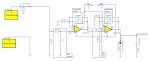
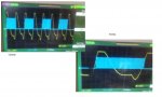
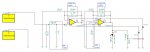
It depends how you've biassed the input to the ADC, but the ADC certainly can't measure a negative voltage (i.e. less than "earth"). In fact the voltage can't even go much below earth (about minus half a volt) because of the protection diodes on the chip (which may be acting as a "dc restoring" clamp). It is indeed "disturbing" that your waveform has a different mark-space ratio to the original "pulse", but if the frequency is correct then the count also should be correct.

Personally, I wouldn't use the "10ms background counter" method for several reasons. Firstly 10ms is a little long, it will only give around 5bpm resolution at high pulse rates (say 180bpm). Also, that timing loop will probably be rather over 10ms. The PICaxe clock should be within about 1%, but PAUSE has been measured to be about 300us (3%) in error and the increment (+ or INC) and loop (JUMP) commands will probably add about 1.5ms (which cannot be decreased by using a higher clock frequency in the multi-tasking mode). A PAUSEUS of about 8000 might get closer.

So, I'd calibrate the rate against your 'scope readings as before, but the choice of the value of calibration constants is quite critical (that's why I had to edit my previous post several times), because it's very easy to exceed the two-byte (16-bit) limit of 65,535. For this reason I wrote some 32-bit maths routines in the "code snippets" section a few months ago (although they're rather more than snippets). However, you shouldn't need them, they're more intended for precise calibration of 10-bit ADC voltage measurements, etc.. You should be able to resolve within about 1%, or 1bpm using only word variables.

Cheers, Alan.
 

JPU

Senior Member
Hi Alan

Thanks for your reply. I will probably have a play with both methods to see what type of results I get once I sort out the current problem!

At the moment I am having a problem with the traces. I am trying to figure out why the circuits does not seam to recognise that the adc value has dropped below 100. However it does then seam to de activate the pin 2 when the adc voltage goes negative.:confused:

Regards

Justin
 

Attachments

JPU

Senior Member
Hi Guys

Here I am back again.

I have resolved the problem with the blue trace. It was todo with clipping in the sensor circuit.

I now have a good trace and all back on track. However, I am struggling to work out how to count the time between pulses, ie this is the time that the blue trace is on or off.

I would like to use Buzby`s idea of Multitasking but I am put off but Alans opinion. However, Alan I can't work out how I can use that method to count between pulses now.

I have included the code and a pic and if you someone could just put me back on track I would be greatful.

Thanks

Justin

Code:
#picaxe 08M2

' Hearbeat


' Symbols
Symbol PulseLED 	= 1

Symbol ADCval 	= b5
Symbol TrigLev 	= b6
Symbol PulseCount = b7
Symbol BPM        = b8
symbol timecount  = b9
symbol sw		= b4
' Code starts here

TrigLev = 100

low 2
							'set pin 2 output to off
' Main loop, repeats indefinately
do


	do						' Stay in this loop until trigger level reached
		
		readadc c.4,ADCval 		'read adc on c.4
			
	loop until ADCval => TrigLev		'loop until trigger level 100 reached
		
		high pulseled
		toggle 2				'start blue trace on scope


		adcval=0
		
		
	do 						' Stay in this loop until below trigger level 
		
		readadc c.4,ADCval		'read adc 
				
	loop until ADCval < TrigLev 		'loop until below triger level
								'switch off blue trace on scope
		Low PulseLED			'switch off pulse led
		
loop ' End of Main loop
 

Attachments

AllyCat

Senior Member
Hi Justin,

I'm still not very happy with your "pulse" waveform but it looks usable for now.

There's nothing wrong with Buzby's code above so I've just "tweaked" it to the way I would start. I've included an optional delay (pauseus) to calibrate the loop period, or just use a multiplier/divisor as we discussed before. Note the use of Word variables where the number of loops (or the period between pulses) may exceed 255. I've added dummy loops to ensure the first value after the program starts is correct, and also that the execution time of the calculations and display do not affect the measurement.

Code:
#picaxe 08M2
#no_data
' Heartbeat

' Symbols
Symbol PulseLED 	= 1
Symbol ADCval 	= b5
Symbol TrigLev 	= b6
Symbol PulseCount = b7
Symbol BPM        = b8
Symbol MyTimer 	= W5
Symbol Duration   = W6
Symbol Calibloop  = 30		; Adjust this to calibrate period or bpm
Symbol Looptime   = 3		; Adjust this to calibrate period or bpm

TrigLev = 100

do         ' Main loop, repeats indefinitely
do
	readadc c.4,ADCval 	
loop until ADCval => TrigLev		; Dummy loop to ensure we start with edge of pulse
do
	readadc c.4,ADCval 	
loop until ADCval < TrigLev		; Dummy loop to ensure we start with edge of pulse

	MyTimer = 0	' Reset timer ready for measurement
	' Find High, Stay in this loop until trigger level reached
do
	readadc c.4,ADCval 
	MyTimer = MyTimer + 1
	pauseus Calibloop			; Optional loop calibration	
loop until ADCval => TrigLev 
	High PulseLED
	
	' Stay in this loop until below trigger level 
do
	readadc c.4,ADCval
	MyTimer = MyTimer + 1
	pauseus Calibloop			; Optional loop calibration	 
loop until ADCval < TrigLev 
	Low PulseLED
	' Now we have seen a pulse, so calculate it's duration

	Duration = MyTimer * Looptime
	
	' Calculate BPM
      '
      ' Put your calc here.
	'
loop ' End of Main loop
I'ver recently contributed to a thread (in finished projects) discussing the execution times of many of the PICaxe commands, but you might find it a bit heavy going for now so a bit of "trial and error" calibrating against your 'scope may be easier.

Cheers, Alan.
 
Last edited:

JPU

Senior Member
Hi Guys

Thanks for you continued help. Allan and Buzby, Thanks for your coding, it has helped me make sense of the necessary tasks. I have now produced a working code that is able to produce a very accurate BPM. I still have a problem in that the BPM can vary from each beat so I will program in a running average,,,later.

I have posted a pic of the scope and also the schematic. Please note I am not an electronics engineer and so the schematic is a mish mash of other peoples work and some additions of my own. I have tried to understand each part of the schematic and I have labelled them with how I understand them? If you see any errors please let me know. The schematic works but has massive room for improvement. Its still a little erratic, but is that due to the fact I am only using 1 sensor and 1 ground across my chest????? I read that most professional ECG machines use many contacts?

If you can help with the schematic then that would be great.

Here is the link to the Tina schenatic file in my drop box:
http://dl.dropbox.com/u/7717360/ECG heart rate monitor using OPA134_sunday.TSC


LEGEND for scope is:

Blue trace show the scope connected to pin 2 on the picaxe
yellow trace is connected to the output from the circuit labelled VF2 on the schematic

Code:
#picaxe 08M2
#no_data
' Heartbeat

' Symbols
Symbol PulseLED 	= 1
symbol sww 		= b4
Symbol ADCval 	= b5
Symbol TrigLev 	= b6
Symbol PulseCount = b7
Symbol BPM        = b8
Symbol MyTimer 	= w7
Symbol Duration   = W6
Symbol Calibloop  = 23		; Adjust this to calibrate period or bpm
Symbol Looptime   = 10		; Adjust this to calibrate period or bpm

TrigLev = 50			'switch used to invalidate negative spikes in the signal
sww=0
do         				' Main loop, repeats indefinitely
	do
		readadc c.4,ADCval		' read the adc value 	
	loop until ADCval => TrigLev		; Dummy loop to ensure we start with edge of pulse
	High PulseLED				; switch on pulse led to signify start of pulse
	
	
	'do                                 ;this has been removed as the picaxe seams to miss this
	'	readadc c.4,ADCval		;due to the time it takes to jump out of the above loop 	
	'loop until ADCval < TrigLev		; Dummy loop to ensure we start with edge of pulse


	sww=0						'return switch to 0
	duration = 0				'reset the duration value
	MyTimer = 0					' Reset timer ready for measurement
	
	do						' Find High, Stay in this loop until trigger level reached
	
		toggle 2				'toggle the pin2 used to time the loop, loop time is 5ms, blue trace
		readadc c.4,ADCval 		'read the adc
		MyTimer = MyTimer + 1		'increment the mytimer count
		pauseus Calibloop			'pause used to calibrate the loop to get the 5ms
		if adcval<20 then let sww=1	: end if 'set the sw to 1 only if the adc has dropped below 30
		loop until ADCval => triglev and sww = 1 ' loop until the adcval is >100 as signifies start of new loop
	low 2						'switch of pin2 , ensuring the pin isnt left high, blue trace off
	Low PulseLED				'switch of pulse led
	
	 
	do						'Stay in this loop until below trigger level 
		readadc c.4,ADCval		'this is necessary as the picaxe will not be fast enough to 
			 				'compute the calculations and measure the next pulse
	loop until ADCval < TrigLev 		'so this will enure a beat is missed while the calcs are done.
	
							'calculations
	Duration = MyTimer * Looptime /2	'miltiply the no of loops * the time for each loop (5ms rounded to 10ms) /2
							'The above is divided by to as we double the 5ms to 10ms to compute
							
							' Calculate BPM
     	bpm=60000/duration			'divide 60000 (no of milisecs in 1 minute) by the duration of the beat
      
      debug						'output results
      
      'unfinnished code to go here. I will calculate an average from the last 5 beats received.
      
	'
loop ' End of Main loop
Thanks for looking.

Edit: I have been looking into the average method I will use, ie rolling average of the last 5 pulse counts. Should I use the scratchpad to do this?? I remember a command from my old BASIC days, that made use of simple arrays eg let a(1)=10, let a(2)=15 etc, does picaxe programming use a similar method???

Justin
 

Attachments

Last edited:

AllyCat

Senior Member
Hi Justin,

Firstly, I must say that I've never attempted to detect heart beats (nor even post circuit diagrams on this forum) so you've done quite well.

However, I think your code is still only measuring part (i.e. the high pulse period) of the whole waveform. That's why you've had to change the multipler (Calibloop) to 10 (when 3 was approximately the correct value). Note that my code had two separate "Mytimer = Mytimer + 1" statements (one for the high part and one for low part of the cycle). Then all the calculation/display takes part during the next complete cycle (which is not measured).

The circuit diagram is a very reasonable first attempt, much of it makes sense and tells us a lot. But I don't understand the purpose of the diodes (D1 and D2) on the input or output, nor what the "voltage pulse source (?)" on the input is or does. Personally, I consider U3 and U4 primarily as "amplifiers" (U3 has a gain of about 100, U4 300) with an unusually "low pass" characteristic (necessitated by the application). The values in the "high pass filter" look to me more like 5Hz (rather high for this application) than 0.5Hz which I believe you have marked.

Others may complain (I'll just mention) that there are "conventions" in schematic design such as: a zero should be used before a decimal point (in case the dp gets "lost") and positive voltage rails should be shown towards the top of the diagram and negative (or earth) towards the bottom (when possible).

Cheers, Alan.
 

boriz

Senior Member
Ah. Now I understand where your -ve signal excursion comes from. You're using a strange split supply. (3.5v and 2.5v ?). This could cause problems with the Picaxe input. Not supposed to go that low. Might need a level shifter or at least a diode clamp.

Otherwise looks like you're making good progress. Try a two element average to start. You don't want to slow the response too much.
 

AllyCat

Senior Member
Not supposed to go that low. Might need a level shifter or at least a diode clamp.
Hi,

Ah, perhaps that's what D2 is supposed to do, but the PICaxe pin should go to the junction of D2 and R9. Or simpler, take the A/D pin to the junction of the LED and R6 (with a somewhat lower voltage threshold set in the code).

Cheers, Alan.
 

Buzby

Senior Member
Slightly OT, but it may improve my input to this thread.

A few months back I bought a little OLED breadboard scope, so I could look at wiggly waves whilst all at sea.

I updated the firmware the other day, and found that the AWG ( Arbitrary Waveform Generator ) now has a preset pattern installed.

It's a heartbeat !.

So now I can accurately and repeatably generate BPMs from 60 upwards.

Cool !.

Cheers,

Buzby
 

Attachments

JPU

Senior Member
HI guys, thanks for your comments.

Buzby, that looks cool!!! I went straight on ebay but I could 't find it.....Where did you get that mini scope???

Alan, Thanks for your comments. I have adjusted the schematic to improve clarity. I am sorry about the errors and as you pointed out, I had incorrectly shown the output to the picaxe. Also the supplies were incorrectly labelled and I am not sure how that happened. They are both 3.9V which I will soon be replacing with 5V. The wave generator and diode at the start near the skintact electrode were there for me to analyse the circuit using the Tina s/ware and neither exists in the real world. I have also attempted to tidy up the rails and now show grounds to the bottom. I have double checked the HP filter and I think it is correct at 0.5hz can you check?

The reason why I removed 1 of the "Mytimer = Mytimer + 1" statements was that it seemed as though the statement was actually missing the event due to the delay in the code running. I have rechecked the timings and it looks ok.

If anyone can help with the array problem, ie a suggestion of what code to use that would be great. As I said I remember array syntax like a(1)=??? ab(1)=????? ab(a)=???? etc but picaxe code is not the same!!

Thanks again..

Justin
 

Attachments

AllyCat

Senior Member
Hi Justin,

Yes, with your values of 4.7uF and 68kohms, the "3dB cutoff" frequency is indeed approximately 0.5Hz, but this can be misleading for measuring "transient" (or pulse/edge) waveforms because there is a significant phase shift at this frequency. For quick "sanity checking", I usually calculate the "time constant" (simply the product of R and C) which is about 330ms in this case. With a voltage step applied to the HP filter, about 63% dies away within a time equal to the time constant (and over 90% in 3 * TC, or 1 second in your case). So the dc level will "drift" very considerably between pulses 1 second apart. That may not affect the bpm that you're measuring, but may explain why the waveform is not really "typical" of a heart beat.

No PICaxe Basic doesn't support arrays, but you can probably achieve what you want with poke and peek. There are many "spare" byte variables which can be addressed via a byte "pointer" (e.g. 30 to 255), so you might use something like the following:

Code:
symbol arraybase = 30
symbol arraypointer = b8
symbol currentvalue = b9

for b1 = 0 to 9
	currentvalue = b1 * 2       ; Arbitary test value
	arraypointer = arraybase + b1
	poke arraypointer,currentvalue    ; Write test value at pointer
next b1
for b1 = 0 to 9
	arraypointer = arraybase + b1
	peek arraypointer,currentvalue
	sertxd(#currentvalue," ")
next b1
Set different arraypointers for other arrays, or something like arraypointer = Y * 10 + X + arraybase for 2D arrays, etc..

Cheers, Alan.
 

JPU

Senior Member
Hi Alan

Thanks for your reply,,,wow. Something just went straight over my head!LOL.

I will spend some time working out what you have just said..I also started a new thread with a similar question. I got a couple of answers there and one by SU was similar to yours. Hippy also replied with a peace of code using bptr. I am going to study all the code given to me as I think its all relevant and usefull.

Thanks for your time with this thread, I appreciate all of you guys helping. I will spend some time developing the project and get back to you with and update. FYI: I have ordered specialist electrodes today from a company that have developed non contact ECG electrodes. I hope to add them to the design and I will keep you posted.

Thanks again for you help..

Just
 
Top