Driving large blue 7 segment display

PaulRB

Senior Member
All,

I've been considering buying these 1.8" 7 segment blue displays from China on eBay.

That's the nearest I have to a data sheet for them. Seems to indicate a Vff of 6.5V for the segments (and half that for the dp).

To drive them, I've been thinking over various options, but like this best at the moment: SAA1064

The project will probably be battery powered. I was thinking of using 6 x AA NiMH cells. These would be connected in series giving 7.2 V for driving the displays, with a tap at either 3.6V or 4.8V to drive the Picaxe and other components.

Page 12 of the SAA1064 data sheet shows I will need a couple of transistors for the multiplexing.

So my questions are:
  1. Is this a sensible solution?
  2. What transistors to use?
  3. Could I use 2 darlington pairs from a ULN28003 instead of the transistors, or, as I suspect, can those only sink current, whereas I need to source it for the common annodes?
  4. There's no mention of current limiting resistors for the segments in the data sheet - does the SAA1064 take care of this for me?

Thanks as always for any help. I have been searching the forum for suggestions and try to find answers that way before posting.

Paul
 

nick12ab

Senior Member
So my questions are:
  1. Is this a sensible solution?
  2. What transistors to use?
  3. Could I use 2 darlington pairs from a ULN28003 instead of the transistors, or, as I suspect, can those only sink current, whereas I need to source it for the common annodes?
  4. There's no mention of current limiting resistors for the segments in the data sheet - does the SAA1064 take care of this for me?
  1. Depends whether you're looking for the easy way (with programming) or the cheapest way.
  2. For the anodes, you will need PNP transistors.
  3. NPN transistors aren't very good for use as a high side driver so the ULN28003 isn't a good solution.
  4. There does not appear to be current limiting. However as long as the supply voltage doesn't exceed the maximum forward voltage of the LED displays then there will be no problems.
 

PaulRB

Senior Member
Depends whether you're looking for the easy way (with programming) or the cheapest way.
Well, both, I thought. The SAA1064 costs only a little more than a Picaxe 20m2 and would save me having to get a picaxe to do multiplexing.
For the anodes, you will need PNP transistors.
I thought so too, but P12 of the data sheet shows NPN! Is that just a mistake do you think?
There does not appear to be current limiting. However as long as the supply voltage doesn't exceed the maximum forward voltage of the LED displays then there will be no problems.
With no proper data sheet, I don't know what the max forward voltage is. I'll have to see if I can find a data sheet for a similar product and hope its the same... My 6xAA NiMH idea would be over by 0.7V. Perhaps I'll just put a diode in there to drop that extra voltage.

Thanks for your help as usual nickab!
 

nick12ab

Senior Member
I thought so too, but P12 of the data sheet shows NPN! Is that just a mistake do you think?
The datasheet doesn't indicate that the MX outputs are active low nor does it indicate that they generate a higher voltage to drive the NPNs so they probably just meant it to represent an active high switch.

I this chip operates by blanking the segment outputs, changing the MX outputs then turning on the segment outputs for the next display rather than turning off the MX outputs, changing the segment outputs then turning on one of the MX outputs then you can use PNPs instead but it will change the order of the displays.
 

AllyCat

Senior Member
Hi,

I would be rather concerned by the apparent lack of any specification for the light output or operating current of the displays.

But, bearing in mind their price, if I wanted to drive them I'd use some "beefy" pnp anode drivers (probably each driven from a BC548 buffer) in a "constant current" configuration (i.e. with emitter resistors) and then the cathodes to the PICaxe directly, or BC548 switches or a driver/darlington buffer chip (depending on what current you need for the brightness, or that the displays will accept). But I'd prefer to drop any excess volts across a current-sensing resistor (and associated transistor) rather than a diode or darlington.

But certainly 7.2 volts seems a sensible supply rail, either 6 x NiMH or a couple of Lithium Ion/Polymer cells. Then either a voltage regulator or tap into the battery chain, depending on the other required functionality.

Cheers, Alan.
 
Last edited:

PaulRB

Senior Member
I would be rather concerned by the apparent lack of any specification for the light output or operating current of the displays.
I may have found a little more here, although its still not a proper data sheet, and there are some apparently contradictory figures.

But, bearing in mind their price, if I wanted to drive them I'd use some "beefy" pnp anode drivers (probably each driven from a BC548 buffer) in a "constant current" configuration (i.e. with emitter resistors) and then the cathodes to the PICaxe directly, or BC548 switches or a driver/darlington buffer chip (depending on what current you need for the brightness, or that the displays will accept). But I'd prefer to drop any excess volts across a current-sensing resistor (and associated transistor) rather than a diode or darlington.
Whoa! Lost me a bit there. Sounds like quite a few extra components. But I think one of your suggestions is to drive the display directly with the picaxe. I thought about that for a while because it would be an interesting programming challenge, especially if the picaxe has to keep the multiplexed displays refreshed while doing other things too. Problem with that idea was that while 20mA per segment would not overload any individual picaxe pin, the overall current would be too much. So darlington drivers would be needed, which is another chip anyway, so why not make that extra chip the SAA1064.

Can you suggest a part number for those "beefy" anode drivers? They will need to provide at least 160mA.

Thanks Alan

Paul
 

IronJungle

Senior Member
Couldn't the PICAXE directly drive each segment just as it would an LED?

BTW - this same supplier offers a 4" 7 segment. Four inches!!! That's big and almost makes me wish I has a use to one.
 

PaulRB

Senior Member
Here's an example you may be interested in
Thanks Marks, I had seen that or similar circuits using the UDN2981A. That would have been the way to go if I was going to multiplex using the picaxe. But as I don't want seconds, the SAA1064 does it with one chip and potentially a cheaper/smaller picaxe. If I wanted to do nothing more than a basic clock, even an 08M2 would do the job!
 

AllyCat

Senior Member
So darlington drivers would be needed, which is another chip anyway, so why not make that extra chip the SAA1064.
Can you suggest a part number for those "beefy" anode drivers? They will need to provide at least 160mA.
Hi Paul,

I've had a look at those data sheets now and the SAA1064 does appear to be a very useful package for the application. I had thought that the LED segments might require more than 20mA, so its 21 mA rating looks ideal. It appears that each cathode driver is a current source, or more specifically three parallel sources of 3, 6 and 12 mA to give some control of brightness or power consumption. Also the "two-phase" drive will give double the maximum brightness of a normal 4x multiplex.

However, I do agree with you and Nick about the poor anode driving application diagram. The ic's 1.5 volt saturation voltage drop and a 0.7 volt VBE will "throw away" about 2 volts of your precious battery voltage. Use a PNP and it looks as if you can drive its base through about 560 ohms, or maybe lower, to the anode driver pin (provided you're using the two-phase mode). This drive requires "active low" so either the pairs of digits will appear exchanged (which can of course be corrected in the software), or you will need to use an inverting transistor (e.g BC548) on each anode driver output.

To use the full current capability, the PNPs may need to carry more than 300 mA (7+ segments x 2 digits x 21 mA). Almost 40 years ago I would have used a BC327 (provided they were switched hard on because dissipation is limited) or BD132, BD140, etc. There are probably many similar devices now, but I believe those are still in production so maybe can be said to have stood the test of time.

Cheers, Alan.
 

Bill.b

Senior Member
This may be of some help. The displays are ASD 230CI witch are 2.74" high. they use 3 LEDs in series for each segment.
unfortunatly these are comman cathode displays, therefore you have to use PNP BC327 drivers on the high side and BC337 drivers on the 7 data lines to the displays.
This project is for a 'days to christmas display'. I can supply the code if require.

daystoxmas.jpg

Bill
 
Last edited:

PaulRB

Senior Member
To use the full current capability, the PNPs may need to carry more than 300 mA (7+ segments x 2 digits x 21 mA). Almost 40 years ago I would have used a BC327 (provided they were switched hard on because dissipation is limited) or BD132, BD140, etc. There are probably many similar devices now, but I believe those are still in production so maybe can be said to have stood the test of time
Alan, you are right, they are still made and there seem to be a large (and for me confusing) number of variations! Excuse my ignorance of transistors...

I have been looking at the variations of BC327 on Farnell UK's website, because that's where I've found availability and a good price for the SAA1064. They seem to have several variants from different manufacturers with slightly different specs. For my application, am I right in saying I don't need a high switching speed (will be a few hundred hertz at most), but will a higher current gain be better? Or should I choose a PNP darlington (they don't seem to cost significantly more)?

However, when Alan got me thinking about the total current draw for these displays, I realised I may have a serious design problem here: if 20mA per segment turns out to be needed for enough brightness, that's up to 320mA in total. Assuming my 6 x NiMH AA cells have a capacity of 2,500 mAH each, the displays will consume that in less than 2 days! I really don't want to have to change/recharge the cells that often. I do plan to dim the displays depending on the ambient light level (with an LDR connected to the Picaxe controlling the segment current output by the SAA1064 via the I2C bus). This should help, but at best would double the battery life. A "wall-wart" power supply would solve this, but I'd rather not have the trailing wires.

Can anyone suggest alternative battery source?

Thanks,

Paul
 

AllyCat

Senior Member
Hi Paul,

For sharp switching edges you need a "bandwidth" of much more than a few hundreds of Hz and some transistor specifications quote the "unity" gain (which is far beyond where the devices are useful), however the speed of the transistors shouldn't be a problem in this application. Similarly any voltage rating should be more than adequate, so yes, a higher gain is probably the best choice (but not worth a premium price). The most important parameter in this application may be a low saturation voltage (drop across the transistors), for which the transistor needs to be driven "hard" (with a base current of perhaps 3% to 5% of the collector current). A darlington requires much lower base current, but the saturation voltage is generally about half a volt more, because of the additional "diode" drop (the base-emitter voltage of the second transitor). The "ideal" component here might be a P-Channel MOSFET, but I've never used one myself and can't recommend a type number.

The difficulty with the design here is that we don't seem to have much data on the voltage characteristic of the displays (I believe just 6.5 volts was quoted). This voltage may be predominantly due to the "knee" of the LEDs, or a significant proportion may be a "resistive" drop. If the displays are fed with a little less than 6.5 volts then with resistive losses the display will be just a little dimmer. But if the knee is quite high then you may get much less current flow (and thus low light output). You might need to measure the I/V characteristics of a few displays when you get them, to optimise the drive circuit.

If you're using 6 x NiMH cells then the (nominal) 7.2 volts doesn't give much "headroom" for the driver circuits (and using a seventh cell would be rather "untidy"). An alternative battery type could be 2 x Lithium Ion (or Polymer) cells, but these have a nominal voltage of 3.6 - 3.7 volts so you'd get a very similar supply rail. They can be more compact than NiMH, but rather more tricky to charge, however it might be worth looking for "7.2 volt battery packs" as used for model cars and planes, etc..

In practice, you might find that much lower than 21 mA/segment is sufficient for many lighting conditions. The intensity of daylight varies over a large range, so even 3 mA may be sufficient for much of the time (it's less than 3 f-stops difference, if you're a photographer).

Cheers, Alan.
 

PaulRB

Senior Member
Well, thanks again Alan. The 1.8" displays are no longer available on eBay, so I ordered some very similar 1.2" instead, also from a Chinese eBay supplier. I've ordered a couple of saa1064 from Farnell too. Just those pnp/p-channel FETs to order now.
 

PaulRB

Senior Member
Hi all, an update for anyone thinking of using SAA1064 in a project:

I have the SAA1064 driver chip from Farnell (good service, but £20 min on credit card orders). I don't have the 1.2 inch displays from China yet, so am practising on 4 yellow single digit smaller displays (also common anode).

First of all, thanks to nick12ab and Alan for the advice on transistors. I'm sure the advice on using PNP, for example BC327, is normally sound, but in this case it didn't seem to work for some reason. The segments lit, but only just visibly. I replaced them with BC635 (NPN) and it now works great. Maybe down to the way NXP/Phillips designed the SAA1064. Although Alan said something about "drive its base through about 560 ohms" with a PNP, which I didn't quite understand and haven't done. Would that have helped?

Secondly, the SAA1064 won't do I2CFAST, only I2CSLOW, which I understand means anything else on the bus also has to be run at the slow speed, even if it is capable of fast.

Thirdly, the SAA1064 data sheet says the minimum supply voltage is 4.5V, but mine is running just fine at 3.8V (3 x AAA NiMH). Maybe I am just lucky with this one.

Fourthly, the SAA1064 is a big fat chip - don't know why - takes up a lot of space on your breadboard!

IMAG0607.jpg

Code:
; SAA1064 7 Seg Display test
; P. Beard 2/5/2012

#picaxe 08m2

; Display symbols 
symbol DISPLAY = $70
symbol DYNAMIC = 1 
symbol ENABLE1AND3 = 2
symbol ENABLE2AND4 = 4
symbol SEGTEST = 8
symbol CURRENT3 = $10
symbol CURRENT6 = $20
symbol CURRENT12 = $40

symbol SEGDATA = 0
data SEGDATA, (%01111011,%00001001,%10110011,%10011011,%11001001,%11011010,%11111010,%00001011,%11111011,%11011011)


main:


		b0 = DYNAMIC+ENABLE1AND3+ENABLE2AND4+CURRENT3
		HI2CSETUP I2CMASTER, DISPLAY, i2cslow, i2cbyte
		HI2COUT 0, (b0)
		do
			for w1 = 0 to 9999
				b0 = w1 / 1000 + SEGDATA
				read b0, b4
				b0 = w1 / 100 % 10 + SEGDATA
				read b0, b5
				b0 = w1 / 10 % 10 + SEGDATA
				read b0, b6
				b0 = w1 % 10 + SEGDATA
				read b0, b7
				HI2COUT 1, (b6, b7, b4, b5)
				pause 100
			next
		loop
		

end
Apologies for the lack of comments in that code!

Also, the binary codes in the "DATA" line at the start of the program will only display decimal digits correctly if you happen to have wired your displays up in the same peculiar way I did!

Paul
 
Last edited:

nick12ab

Senior Member
Secondly, the SAA1064 won't do I2CFAST, only I2CSLOW, which I understand means anything else on the bus also has to be run at the slow speed, even if it is capable of fast.
That is correct. The SAA1064 could get confised if you try to communicate with the other devices using i2cfast however you would get away with 'overclocking' the bus beyond i2cfast most times anyway but that luck wouldn't last forever!


Fourthly, the SAA1064 is a big fat chip - don't know why - takes up a lot of space on your breadboard!
This could be because of the internal heat spreader inside the chip.
 

AllyCat

Senior Member
Maybe down to the way NXP/Phillips designed the SAA1064. Although Alan said something about "drive its base through about 560 ohms" with a PNP, which I didn't quite understand and haven't done. Would that have helped?
Hi Paul,

Looking again at the data sheet it appears that the SAA anode drivers are emitter followers, so there would be little/no pull-down current to directly drive the PNPs. A pull-down resistor of a few hundred ohms (on the SAA output pin) would probably suffice, but is not particularly efficient. However, the PNP configuration will only show its advantage/necessity when/if the voltage drop across the displays approaches 6.5 volts (i.e. within about a volt of the supply rail).

If you discover that the "real" displays are too dim (they may have more voltage drop because they contain several LEDs in series) then the PNP configuration should have the emitter to supply rail and collector to the display anode(s). There are several ways to drive the base, but IMHO the simplest configuration is a small NPN driver transitor (e.g. BC548) with base to the SAA anode driver pin, collector to the PNP base and a resistor of about 560 ohms from NPN emitter to ground. Note this is a slightly unconventional configuration, some people might prefer an NPN grounded emitter "inverter" with resistors in series with base and collector.

The chip is probably quite an "old" design (definitely Philips not NXP) but as Nick says, the large package is probably to dissipate the significant amount of heat inherent in the design (e.g. linear current sources), without the need for an additional heatsink.

Cheers, Alan.
 

nbw

Senior Member
Another possibility for the power supply - if you run a low voltage PICAXE (3.3V) is to use 2 x 3.7V Li-ion batteries in series. These would give you around 8V fully charged and just over six when getting a bit tired.

If you had about 12 digits, you could make a US debt display :)
 

PaulRB

Senior Member
The displays arrived today! Faster than I expected. I was a little disappointed when I had to settle for the 1.2" instead of the 1.8", but now they've arrived, I'm glad they're not any bigger than they are:IMAG0608.jpg
Now to test them...
 

PaulRB

Senior Member
Update: making some progress. Finally got the large displays working after many attempts. Not sure what I was doing wrong. Still using the BC635 NPN transistors for multiplexing/switching.

Unfortunately, I have had to move up to using 7 x AA NiMH. I guess Alan was right about the voltage drop caused by the driver chip and the transistors. With 6 cells, only the decimal place LEDs will light. 7 is an awkward number of cells, so I may try with 8.

Also, suspect I have damaged some of the segments - "singed" them slightly with too much voltage/current while testing. Some are noticeably dimmer than others. I may have to order replacements from China before final assembly. Still, they were only a tenner for 4, with free P&P too.

Have also wired up the ULN2803 driver chip and 5 solenoids which will eventually strike chimes cannibalised from a wind chime. Despite a 470uf cap across the supply rail, the display dims momentarily when they are activated.

I am trying to upload a short video to youtube, but in the mean time, here's a picture and the latest code.

Many thanks again everyone for the help so far!

Paul

IMAG0610.jpg

Code:
; Clock
; P. Beard 2/5/2012

#picaxe 20m2
#terminal 4800

; Picaxe Pin symbols
symbol	SPKR = B.0
symbol	LDR = B.2
symbol	IR = B.1
symbol	CHIME0 = C.0
symbol	CHIME1 = C.1
symbol	CHIME2 = C.2
symbol	CHIME3 = C.3
symbol	CHIME4 = C.4
symbol	CHIME5 = C.5
symbol	CHIME6 = B.6
symbol	CHIME7 = C.7
symbol	DOORBELL = PINC.6

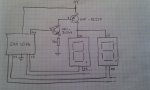
; Display symbols (SAA1064 Display Driver)
symbol	DISPLAY = $70 ; I2C slave address
symbol	DISPLAYSETTINGS = %00000111 ; Dynamic; all digits enabled; test mode off
symbol	BRIGHTSETTINGS = %01110000 ; bits controlling display brightness

; RTC symbols (Jungletronics DS1338 based module)
symbol RTC = $D0 ; I2C slave address

; Data to translate numbers 0..9 into decimal digits on 7 seg display
symbol	SEGDATA = 0
data      SEGDATA, (%01011111, %00000101, %10011011, %10001111, %11000101, %11001110, %11011110, %00000111, %11011111, %11001111)

; irin command symbols
symbol SETTIME = 10 ; ">10" button on remote
symbol TICKONOFF = 17 ; Vol - button on remote
symbol NOCOMMAND = 255

; Program variables
symbol	RTCsecs = b6
symbol	RTCmins = b5
symbol	RTChours = b4
symbol	DISPHoursTens = b8
symbol	DISPHoursUnits = b9
symbol	DISPMinsTens = b10
symbol	DISPMinsUnits = b11
symbol	TickOn = bit16
symbol	ColonOn = bit17
symbol	InputValue = b20
symbol	MaxInputValue = b21
symbol	InputValuePosition = b22
symbol	CHIMEPULSE = 2000

main:

	setfreq m4

	; Set time on RTC 
	'HI2CSETUP I2CMASTER, RTC, i2cslow, i2cbyte
	;HI2COUT 0, (<secs>, <mins>, <hours>, <dow>, <day>, <month>, <year>, <control bits>)
	'HI2COUT 0, ($00, $50, $12, $07, $09, $06, $12, $14)
	TickOn = 1

	do
		
		; Read current time from RTC
		HI2CSETUP I2CMASTER, RTC, i2cslow, i2cbyte
		HI2CIN 0, (RTCsecs, RTCmins, RTChours)		

		; Write time to display, converting from BCD to decimal digits
		DISPHoursTens = RTChours / $10 + SEGDATA
		read DISPHoursTens, DISPHoursTens
		DISPHoursUnits = RTChours & $0F + SEGDATA
		read DISPHoursUnits, DISPHoursUnits
		; Flash colon (actually just decimal point on this display)
		ColonOn = not ColonOn
		DISPHoursUnits = 32 * ColonOn | DISPHoursUnits
		DISPMinsTens = RTCmins / $10 + SEGDATA
		read DISPMinsTens, DISPMinsTens
		DISPMinsUnits = RTCmins & $0F + SEGDATA
		read DISPMinsUnits, DISPMinsUnits
		; Dim display depending on light level
		readadc LDR, b0
		b0 = b0 / 2 + 16 & BRIGHTSETTINGS | DISPLAYSETTINGS
		HI2CSETUP I2CMASTER, DISPLAY, i2cslow, i2cbyte
		HI2COUT 0, (b0, DISPMinsUnits, DISPMinsTens, DISPHoursUnits, DISPHoursTens)


		; Chime & tick only between 7am and 11pm
		if RTChours >= $07 and RTChours <= $22 then
			; Make "tick" sound if enabled
			if TickOn = 1 then : pulsout SPKR,  10 : end if
			if RTCsecs = $00 and RTCmins = $00 then
				; Worst version ever of "Westminster Chimes"
				sound SPKR, (120, 100, 115, 100, 110, 100)
				; "Bong" the hours (convert hours from BCD into 12 hour time: we don't want 22 bongs at 10pm!
				b0 = RTChours & 15
				b0 = RTChours / 16 * 10 + b0
				if b0 > 12 then : b0 = b0 - 12 endif
				For b1 = 1 to b0 
					sound SPKR, (0, 100, 80, 100)
				Next
			else if RTCsecs = $00 and RTCmins = $15 then
				; Chime at quarter past
				sound SPKR, (110, 100, 115, 100, 120, 100)
			else if RTCsecs = $00 and RTCmins = $30 then
				; Chime at half past
				sound SPKR, (120, 100, 110, 100, 115, 100)
			else if RTCsecs = $00 and RTCmins = $45 then
				; Chime at quarter to
				sound SPKR, (100, 100, 120, 100, 115, 100)
			endif			
		endif			

		; Check for IR commands & doorbell push
		for b1 = 1 to 5
			b0 = NOCOMMAND
			irin [100], IR, b0
			'pause 100
			'sertxd ("IRIN=", #b0, 13, 10) 
			if b0 <> NOCOMMAND then gosub ProcessIRCommand

			if DOORBELL = 0 then gosub RingDoorbell
		next
		
	loop
	
RingDoorbell:

	pulsout  CHIME0, CHIMEPULSE
	pause 200
	pulsout  CHIME1, CHIMEPULSE
	'pause 200
	pulsout  CHIME2, CHIMEPULSE
	pause 200
	pulsout  CHIME3, CHIMEPULSE
	pause 200
	pulsout  CHIME4, CHIMEPULSE
	'sound SPKR, (90, 100, 120, 50, 110, 50, 100, 50)
	return


ProcessIRCommand:

	sound SPKR, (125, 2)
	pause 250
			
	if b0 = TICKONOFF then

		TickOn = not TickOn

	else if b0 = SETTIME then
				
		; Allow user to enter time
		HI2COUT 1, (8, 8, 8, 8) ; clear display
		; read tens of hours
		MaxInputValue = 2
		InputValuePosition = 4
		gosub GetInputValue
		RTChours = InputValue * $10
		; read units of hours
		if InputValue = 2 then : MaxInputValue = 3 : else : MaxInputValue = 9 : endif
		gosub GetInputValue
		RTChours = RTChours | InputValue
		; read tens of mins
		MaxInputValue = 5
		gosub GetInputValue
		RTCmins = InputValue * $10
		; read units of mins
		MaxInputValue = 9
		gosub GetInputValue
		RTCmins = RTCmins | InputValue
				
		; Set time on RTC and zero the seconds
		HI2CSETUP I2CMASTER, RTC, i2cslow, i2cbyte
		HI2COUT 0, (0, RTCMins, RTCHours)
		sound SPKR, (110, 2, 0, 2, 120, 2)

	endif

	return

GetInputValue:

	do
		; read a value from IR remote
		irin IR, InputValue
		if InputValue >= 0 and InputValue <= 9 then
			InputValue = InputValue + 1 % 10
			if InputValue <= MaxInputValue then
				; digit OK
				sound SPKR, (125, 2)
				exit
			else
				; digit not allowed
				sound SPKR, (75, 2)
			end if
		else
			; not a digit
			sound SPKR, (75, 2)
		end if
	loop
	
	; Update display with input value
	b0 = InputValue + SEGDATA
	read b0, b0
	HI2COUT InputValuePosition, (b0)
	dec InputValuePosition
	pause 250

	return

end
 

AllyCat

Senior Member
Hi Paul,

IMHO a couple of resistors, PNP LED drivers (e.g. BC327) and NPN inverter/pre-drivers (e.g. BC548) should come in cheaper than another battery (or two). ;) As the drivers in the ic are "linear", the extra voltage will just be converted into heat.

The cathode drivers in the ic are current sources, so that shouldn't have damaged the LEDs and to be honest I'd expect them, if damaged, not to work at all. The "quality" of Chinese/ebay items always has to be considered "suspect" (although I've certainly received some real "bargains") so maybe the non-uniformity is why they're "cheap". Can you test them with a known good current drive, for example each segment driven separately through typically a 270 or 330 ohm resistor directly from a 9 volt supply (i.e. around 10mA/segment)? Or even taking the LED anodes directly to a 7.2 volt supply (with cathodes connected via the ic drivers) should be "safe".

Cheers, Alan.
 

PaulRB

Senior Member
Alan, sounds worth a try to avoid extra batteries, so let me see if I have understood your suggestion:
IMAG0612.jpg
I don't have any bc548, but I do have those bc635. Will those do instead?

So how will this help exactly? Will there be less voltage drop across the pnp in that config compared to the npn I have now?

Cheers,

Paul
 

AllyCat

Senior Member
Hi Paul,

Yes, that was the configuration I Had in mind. Perhaps add a medium value resistor (say 2k2), if available, between PICaxe and base, at least on the test rig, in case of "accidents".

The BC635 is not "ideal" because it has rather a low minimum gain (hFE = 25 at 5mA) but should work OK, as should any cheap, general purpose, small signal NPN transistor that you may have to hand.

The modified configuration "saturates" the PNP so its collector should be less than (say) 0.5 volts below the supply rail. I believe the SAA data specifies an output voltage nearer 1.5 volts below the supply rail and then the NPN emitter follower drops at least another 0.7 volts, so the LED anodes will be seeing at least 2 volts below the supply rail. Therefore, the modified circuit should "save" at least one cell.

Cheers, Alan.
 

PaulRB

Senior Member
It works! Thankyou Alan.

The displays are now running off 6 cells. The unevenly lit segments are also much less noticeable.

I had no 560R so used 510R. Just under 3V drop across them, so 6mA through each.

However, this pales into insignificance compared to the current consumed by the displays. At lowest (3mA per segment) that's up to 66mA, and at 12mA per segment that's 264mA. My DMM bears this out: the rest of the circuit only consumes 10-20mA.

So my 2000mAH cells will last 10 to 30 hours. I am back to thinking about an alternative power supply again!
 

PaulRB

Senior Member
Or multiplex them. That could save 3/4 of your power. One of the reasons for multiplexing is that only one display is on at a time.
Pete, they are multiplexed: 2 digits on at any time. The saa1064 chip won't do 1 in 4 multiplexing, so I would need a completely different setup (eg. another picaxe, high and low side driver chips) and it would only double battery life at best.

I'm searching the house for wall-warts saved from old defunct appliances. Have found a couple of 9V ones...
 

AllyCat

Senior Member
Hi Paul,

Be careful that 9 volt "plug in" supplies might not be regulated, the voltage could rise dangerously when only a few segments are driven.

Reducing the power will reduce the brightness! If that is acceptable (all or part of the time) then you might use PWM to drive the displays. Do you have one or more spare (PWM) pins on the PICaxe? If so, just take the lower (currently grounded) end of the 560 ohm resistor in the emitter of the driver transistor(s) to a PICaxe pin*. That would give "active low" drive, so the segments will dim as the PWM is increased. But you might need to choose the PWM frequency carefully to avoid low frequency "beating" (flicker) with the multiplexing frequency.

*EDIT: I'd forgotten that the SAA chip is "15 volts tolerant" and is running on a higher supply voltage. That simple PWM drive arrangement is potentially "dangerous" for the PICaxe chip if the output voltage from the SAA (anode driver pins) is significantly higher than the PICaxe supply rail. There are various ways to protect against that: A simple method would be (say) 10k between the SAA pin and NPN base, but operating the SAA from the (5 volt) PICaxe supply could be the best solution now (since only the PNP needs to be on the "anodes" supply rail.

Cheers, Alan.
 
Last edited:

PaulRB

Senior Member
Thanks as always Alan. I was aware of the potential non-regulation of the 9V adaptor and will do some testing with a pot and DMM. If regulated to 9V, will current sources in saa1024 protect the displays from damage from the extra voltage, do you think? Or do I need to put my own regulator in to reduce down to 7.5V? Obviously I will need 5V reg for picaxe. I could then run saa1024 off either rail, if there is any advantage. Not really interested in dimming displays further, as chip has s/w brightness control (7 levels) and ultimately it will be behind blue stained-glass panel which may also reduce apparent brightness. Thanks for the pwm idea anyway.
 

AllyCat

Senior Member
Hi Paul,

Yes, the SAA should protect the displays from excess voltage. However, you need to consider the power dissipation in the chip if you're using the maximum (20mA) brightness levels. All segments driven could take almost 300mA, so a 3 volt drop in the ic would dissipate almost a watt which is the upper specification of the device.

The simple rule is "if you can't bear to keep your finger touching an electronic component, it's probably dissipating too much power" (not a recommended method for mains equipment). ;)

Cheers, Alan.
 

PaulRB

Senior Member
Maybe that's where the phrase "rule of thumb" came from!

But suspect 3mA or 6mA will be enough except bright sunny days. Even then, i could limit to 12mA or 15mA in software.
 

PaulRB

Senior Member
After testing 4 old 9V "wall warts", one turned out to be regulated and claims to provide 500mA, which should be more than enough.

With the addition of a 78L05 providing 5V for picaxe and rtc, the circuit is now running from the 9V supply. Segment brightness is now very even. All components remaining cool. There is a just noticeable warming of the wall wart and the saa1024, barely enough for fingers to detect.
 

PaulRB

Senior Member
The BC635 is not "ideal" because it has rather a low minimum gain (hFE = 25 at 5mA) but should work OK, as should any cheap, general purpose, small signal NPN transistor that you may have to hand.
Alan, I've just had a thought: I have 2 unused darlingtons in the ULN2803. Could I use those instead of the npn transistors? I.e. mx output from the saa1064 to darlington input, then darlington output to pnp's base via 510R resistor. This would remove a couple of components!
 

AllyCat

Senior Member
Hi Paul,

Yes, in principle I think Darlingtons should work alright, but I don't know what the other Darlingtons in the package are doing.

I'm not sure which configuration you're using now, but with the (NPN) emitters grounded you probably need a resistor between the SAA output(s) and the Darlington inputs. IMHO the "symbol" for the ULN is rather misleading (if it really contains darlington-connected transistor pairs).

Note that you must also connect the rail for the "Catching" (or protection) diodes in the ULN to the full supply rail (i.e. the emitters of the PNPs).

Cheers, Alan.
 

hippy

Ex-Staff (retired)
The simple rule is "if you can't bear to keep your finger touching an electronic component, it's probably dissipating too much power" (not a recommended method for mains equipment). ;)
Though some chips are designed to run quite hot. I believe 50C is too hot to touch for long and, because of the risk of injury - or consequences of reaction when hotter than anticipated - it's not a recommended practice.
 

PaulRB

Senior Member
Thanks Alan,

5 of the other darlingtons are driving solenoids which will strike chimes. Their inputs are wired directly to picaxe outputs. The code pulses them for ~20ms once or twice every 15 mins. The other 3 are currently unused. Yes, the common pin on the 2803 is connected to the 9V supply rail.

The pnp and npn transistors are currently exactly as you suggested earlier, as per my diagram. Why the suggestion for extra resistors on mx outputs? Could the darlingtons effectively short the mx outputs to ground? If so, could that also happen to picaxe outputs?

Paul
 
Top