Project hiccup and need help please

bfgstew

Senior Member
Hi, I am new to picaxe and hope to solve a puzzle.
I have been following and making the following project - http://diyphotography.net/create-an-automated-macro-rails-for-image-stacking.
I have followed the instructions to the letter but it still doesn't want to play ball.

Firstly, even after checking the motor wires for the correct sequence, it didn't run.
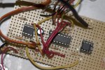
I eventually got the motor to run and controlled with the remote, but the optocoupler didn't fire my camera?
Now the motor has stopped running again, it just sits there buzzing.

The only things different to the parts used is I am using the Y129-5 ASTROSYN motor and IR receiver from tech supplies.

I hope you can help as it is getting very frustrating as I can't see where I have gone wrong. I am a multi skilled engineer and am adept with wiring, soldering, drawings and the like, just the programming part is a mystery to me, the code I used has just been copied and pasted from the link, but I have done a syntax check and simulation and they come up with no errors.

Cheers in advance.

Stewart
 

Armp

Senior Member
The only things different to the parts used is I am using the Y129-5 ASTROSYN motor and IR receiver from tech supplies.
' Black +12V
' White +12V
' Yellow output7
' Red output6
' Brown output5
' Orange output4
Looks like it needs 12V? The original design used a stepper from an old floppy drive, maybe that was 5V?

And I'd beef up the single 0.1uF decoupling cap as well...
 

hippy

Technical Support
Staff member
If so, start to build from scratch.
It will also help to treat the motor and camera opto-coupling as separate entities until you have both working separately. Get PICAXE code for each working while debugging any issues of hardware and software separately.
 

bfgstew

Senior Member
Eclectic - I will post a photo ASAP, I know what you'll say when you see it though......LOL, and yes that is the motor in question.

Armp - I have had it running off 5V, it just judders now!!!! 12V, will the 08M2+ chip take that? If so will I be able to use an AC/DC adapter? What size cap to replace the 0.1uF one?
 

bfgstew

Senior Member
Hippy - It seems everyone else can build this with ease and get it working straight away. I on the other hand, end up chasing my tail over something that will no doubt be so simple it will make me weep................:(

I did do another simulation run on it, between posts, just to see. and I did notice the output of the 08M2, which goes to the opto coupler, stays olive green, unlike the motor outputs which are a lime green, does this mean anything??????
 

geoff07

Senior Member
It can be very frustrating. One thing you could do is write a test program whose job is simply to test each item of hardware, flash the leds, move the motor, etc one after the other. That would either find the problem or give you the confidence that the problem was not in the hardware. It is always a good idea to do this if the hardware is complex. Once you know the hardware is right, you can test the software, section by section, making simple main program loops to test each subroutine to make sure it does what you want. By the end of all this you won't be a novice any more.
 

Armp

Senior Member
Armp - I have had it running off 5V, it just judders now!!!! 12V, will the 08M2+ chip take that? If so will I be able to use an AC/DC adapter? What size cap to replace the 0.1uF one?
The 08M2 won't take 12V, I'm not even sure if the present 4 x NiMh is really within spec?

I'll hold further comments until we see the photo!
 

hippy

Technical Support
Staff member
I did do another simulation run on it, between posts, just to see. and I did notice the output of the 08M2, which goes to the opto coupler, stays olive green, unlike the motor outputs which are a lime green, does this mean anything??????
Perhaps that you're not running the simulation correctly ? Entering 21 into the generic field to simulate pressing the power key when read by INFRAIN2 seemed to have pin 4 flashing as an output on 08M and 08M2.

As the code seems to work, works for others, and 08M2 execution seems to be the same for 08M, it would be a fair bet to think it's more of a hardware / mechanical / circuit / wiring issue rather than software. For the opto part I'd suggest a simple test loop -

Do
High 4
Pause 1000
Low 4
Pause 5000
Loop

And then start to check the hardware, see if voltages in the circuit are correct etc.
 

bfgstew

Senior Member
Hippy - have done the test you posted and the output does change, tested on set up and am getting 5V at the opto coupler, but its still not triggering the camera. I have tried checking the output signal with a multimeter but I think it is to slow to catch the signal?..............Hmmmmmmmmm Is there a simple way of checking the output?
 

KeithRB

Senior Member
What camera? How are you connecting it? Have you tried triggering the optocoupler manuallly to make sure it fires the camera?
 

hippy

Technical Support
Staff member
I don't know if it's possible to check the opto output with a DMM with a continuity test or a resistance measurement ( red to collector, black to emitter ) but emitter to 0V and collector to LED+R to +V should have it flashing on ( or blipping off ? ) for a second every 5 seconds. You can tweak the PAUSE times as desired.
 

bfgstew

Senior Member
Nikon D200 using 10 pin remote release cable wired onto the outputs 4 and 5 of the opto coupler.

Here is a shot of the offending article...........

rail.jpg
 

eclectic

Moderator
Have you checked that the camera fires
on a simple switch press?

I've got a Nikon D200 connected to a
MC25 adapter thence connected to a
cannibalised MC12A trigger switch.

Shorting the two wires fires every time.

e
 

bfgstew

Senior Member
Yes, if I short across the 2 wires the camera fires!

Methinks I may have to start again, the layout is a bit of a mess, so will re think the layout so it is less confusing and cluttered, new 4N25 opto as I think it is dud.

Just need to sort this motor problem out now.............:(
 

eclectic

Moderator
Yes, if I short across the 2 wires the camera fires!

Methinks I may have to start again, the layout is a bit of a mess, so will re think the layout so it is less confusing and cluttered, new 4N25 opto as I think it is dud.

Just need to sort this motor problem out now.............:(

As one of the components of your project,
have a look at Manual 3, page 15-16.

Then, when you have a new optocoupler
(or even try the present one)
build a very simple timer circuit
which fires the camera say every 1 second.

You'll get plenty of advice if you decide to proceed.

e
 

Armp

Senior Member
It should go to pin 5 of the 08M2 I think. But the wire from pin 11 should go to 1 not 2

ScreenShot.jpg


I did an edited screenshot as a jpg!!!! Thanks guys....
 
Last edited:

bfgstew

Senior Member
Armp and Eclectic - cheers for the info and corrections. Just altered wiring to diagram and still no good, motor just judders!!!!!!!
Going to take it off and check wiring sequences again, just to make sure.
Thanks once again guys, appreciate all the help.
Stewart
 

bfgstew

Senior Member
Right, took motor off to check sequence as desribed in link on first post, now do I need to do this for this motor??? Because I did as described, put it back on and it still doesn't run.......!!!!!!
I read the above diagram and have re drawn the circuit roughly, just need to condense it onto some variboard. I will post it later on today to get some feedback on it.
What is the best way to to get both 5VDC and 12VDC onto my board? 5VDC is easy with a battery pack, would I need to use a transformer to step down to 12 and 5vdc so as not using batteries?
 

eclectic

Moderator
Right, took motor off to check sequence as desribed in link on first post, now do I need to do this for this motor??? Because I did as described, put it back on and it still doesn't run.......!!!!!!
I read the above diagram and have re drawn the circuit roughly, just need to condense it onto some variboard. I will post it later on today to get some feedback on it.
What is the best way to to get both 5VDC and 12VDC onto my board? 5VDC is easy with a battery pack, would I need to use a transformer to step down to 12 and 5vdc so as not using batteries?

Did you actually get the motor rotating with the RevEd circuit and code?

e
 

bfgstew

Senior Member
Eclectic - I downloaded the test code but nowt happened?

Does it need to be built on new circuit or can it be tested on exsiting circuit?
 

eclectic

Moderator
Eclectic - I downloaded the test code but nowt happened?

Does it need to be built on new circuit or can it be tested on exsiting circuit?
OK, start again.

Use Manual 2 page 16.
Build the basic Picaxe download circuit. Man 1 p.8
Add a 100nF capacitor between V+ and Gnd.


Then add the circuit in Man 2 p.16
and use the code on that page.

e
 

bfgstew

Senior Member
Okey Dokey e - it may take a while but as soon as I get a result, will post back, cheers.
Stewart
 

bfgstew

Senior Member
Eclectic - Ok, have built test rig and downloaded code as suggested, and after changing the wires over on the motor it started to 'step' in one direction!
What's the next step....................:D
 

eclectic

Moderator
Here's a starter:
Code:
#picaxe 08M2
symbol delay = 100 ; alter as required
symbol ticks = b0

Start:

CW:
Let pins = 0
For ticks = 1 to 20
 toggle 2 
pause delay ‘ Wait 
toggle 1 ‘ 
pause delay 
next

ACW:
Let pins = 0
For ticks = 1 to 20
toggle 1 
pause delay 
toggle 2
pause delay 
next

goto start
Got to go out soon, so it's uncommented.

Have a play with the values.

e
 

bfgstew

Senior Member
Eclectic - works like a dream, altered values and can get it to go slow, fast and numerous revolutions, so it looks like the chip and motor are ok.
Now to add the IR receiver into the circuit and see if i can get that to control the motor, if ok, will add the opto coupler and see if i can get the camera to fire, so looking good.
Many thanks for your help, it is much appreciated.
Stewart.

Just out of intrest, can the motor be ramped up from dead slow to a high speed, then ramped down to a slow stop, if so what code would be needed?

Cheers once again.
 

eclectic

Moderator
Eclectic - works like a dream, altered values and can get it to go slow, fast and numerous revolutions, so it looks like the chip and motor are ok.
Now to add the IR receiver into the circuit and see if i can get that to control the motor, if ok, will add the opto coupler and see if i can get the camera to fire, so looking good.
Many thanks for your help, it is much appreciated.
Stewart.

Just out of intrest, can the motor be ramped up from dead slow to a high speed, then ramped down to a slow stop, if so what code would be needed?

Cheers once again.
Very rushed. I'm off out soon.

Alter the Delay values and increments

Code:
#picaxe 08M2
symbol delay = b10; alter as required
symbol ticks = b0
Start:
delay = 5; *****************

CW:
Let pins = 0
For ticks = 1 to 100
 toggle 2 
pause delay ‘ Wait
delay = delay + 10 ; vary  + or - ************** 
toggle 1 ‘ 
pause delay 
next

ACW:
Let pins = 0
For ticks = 1 to 100
toggle 1 
pause delay 
delay = delay - 10 ;************************

toggle 2
pause delay 
next
goto start
 

geoff07

Senior Member
Just a small thing, but it might save some mechanical effort - (some) Nikons can be triggered by an IR signal. All you need is an IR led and some simple code that is on the forum or I can provide. Less wiring, no bounce issues, dead easy. If yours works with IR it is worth a look. I have a turntable that uses this to create web movies.
 

bfgstew

Senior Member
Well, some sort of success, i have now got the unit working!!!!!!!!!! Hurrah, only need to get the opto to trigger now.......boooooo.

I still don't know if there is a error in the code for the opto and as I am a complete novice on codes I hope someone can check it for me please. I will carry on checking this end to see if I can sort it out.
Many many thanks for all your help.
Stewart
 

bfgstew

Senior Member
Am I being daft, but I always thought a resistor should go on the + side of a circuit? On the diagram on #1 post it shows on the - side????
Should it be like this and what value should the resistor be.
untitled.JPG
 

eclectic

Moderator
In the meantime, here is a rough bit of code I
found from when I was building a similar device.

At the moment, there's an LED which lights on pin4

Code:
#picaxe 08M2
; Pins 1 + 2 = stepper
; Pin3 = IRIN
; Pin4 = Trigger
; remote codes P+ =16 / P- =17 / 1 = 0 / 3 = 2
; Remote code (off) = 21 (Fire)
symbol delay = b10; alter as required
delay = 5
Symbol Trigger = C.4

Main:
Irin 3, Infra
sertxd (#Infra, "  ", #Delay, cr,lf) ; for testing
If Infra = 16 then
Delay = Delay + 1 MAX 254
endif

If Infra = 17 then
Delay = Delay - 1 MIN 5
endif

If infra = 0 then
gosub CW
endif

If infra = 2 then
gosub ACW
endif

If Infra = 21 then
High trigger
Pause 500 ; alter *****
Low trigger
endif

GOTO main

CW:
;Let pins = 0
 toggle 2 
pause delay 
toggle 1 
pause delay 
Return

ACW:
;Let pins = 0
toggle 1
pause delay 
toggle 2
pause delay 
Return
e
 
Top