OT: Charlieplexing - my head hurts !

Buzby

Senior Member
Hi All,

I need to light any three LEDs from a group of 240.

The lowest hardware solution seems to be Charlieplexing using 16 I/O direct from a PICAXE.

The LED current is reasonably low, and I only need 3 LEDs lit, so no need to scan the whole matrix all the time.

The software is going to be tricky, but I can't start until I know what the matrix looks like, and this is where I'm struggling.

Trying to draw a circuit diagram for the LEDs is getting complicated, and I need a much bigger sheet of paper !.

Does anyone know if there is any software that makes designing the matrix a bit easier ?. Even just a point-to-point wiring list would be OK.

Cheers,

Buzby
 

John West

Senior Member
Are you prepared to do a sophisticated PCB layout? If this is a "just one" build, it might not be worth the design effort required to go with the Charlieplexing.

I'm just suggesting. I'm not experienced with the practical details of Charlieplexing. I just read about it and would tend to shy away from its use if there were so many LED's involved.

Having made too many wiring errors in my life I tend to try to keep everything as simple as possible, even to the extent of paying more for parts than is absolutely essential. It also makes troubleshooting much easier. Troubleshooting a large Charlieplexed circuit could be quite tedious.
 

slimplynth

Senior Member
Hi Buzby.. that sounds like a lot of LEDs to charlieplex... I'd imagine that that wiring/circuit would look as impressively complex as the code to drive it all.

Its been ages since I tried it, on a breadboard, starting with 6 LEDS but if i were thinking about multiple LEDs again I'd spare my sanity a little by using a proper LED driver chip, like the below..

http://www.maxim-ic.com/datasheet/index.mvp/id/3503
 

Buzby

Senior Member
@eclectic, the LEDS are in a circle - but it's not yet another clock !. The MM5450 chip is definitely the most cost effective hardware solution. Using these I could drive the LEDS at a cost of about £28, - but Charliplexing does it for £0 !.

@slimplynth, yes, it is a lot. That's exactly the reason I want to use Charlieplexing. Any kind of hardware will cost too much.

!!! Eureka, I've just seen I don't need Charly.

I only need a couple more I/O pins apart from the LEDs, so if I use a 40X2 I can use a 15 x 16 standard multiplexer, using 31 pins, and still have a pin or two left over.

It's good to talk through ideas here on the forum, sometimes I can't see the wood for the trees.

Thanks !.
 

hippy

Technical Support
Staff member
Trying to draw a circuit diagram for the LEDs is getting complicated, and I need a much bigger sheet of paper !
It shouldn't be that hard if you notice what the pattern is with Charliplexing. Start with a standard N x M matrix ...

Code:
--------|-------|-------|-
      \ |     \ |     \ |
        |       |       |
--------|-------|-------|-
      \ |     \ |     \ |
        |       |       |
--------|-------|-------|-
      \ |     \ |     \ |
        |       |       |
Then you need to connect the columns back to rows, and that 'erases' one of the possible LED's at the row-column join ...

Code:
--------|-------|--.----|-
      \ |     \ |  |    |
        |       |  |    |
--------|--.----|--|----|-
      \ |  |    |  |  \ |
        |  |    |  |    |
---.----|--|----|--|----|-
   |    |  |  \ |  |  \ |
   |    |  |    |  |    |
   `----'  `----'  `----'
And as you can see it's quite simple, with the columns to row links going up a row as we move from left to right, and a diagonal of missing LED's.

Scale up until you have enough LED's. Voila !


PS : Can anyone recall how to get an MS-DOS application under XP to give | (unsplit) rather than ¦ (split) when the bottom left "¦ above \" key is pressed ?

It works at the Command prompt ( shows an unsplit bar ), as it does in Notepad, but run my text editor and it swaps them. I had it working, but some setting / tweak / hack I did on my old PC didn't get carried through when I upgraded, and it's now starting to really annoy me !

Removed all 'code page' stuff from AUTOEXEC.BAT, CONFIG.SYS, tried numerous web suggestions but it's still not right. It's probably written down somewhere, but so are a lot of things I can no longer find. Grrr.
 

Buzby

Senior Member
Hi eclectic,

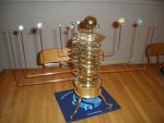
Here's one I built earlier, but not using a PICAXE.

I want to build one that can hang on the wall.

I'm still deciding between circles of LEDs with a bag of software, which I know can do, or some clever electro-mechanical system, which I've no idea yet how to go about.

First I'll decide on the result, then I'll work out how to make it !.

Cheers,

Buzby
 

Attachments

eclectic

Moderator
Hi eclectic,

Here's one I built earlier, but not using a PICAXE.

I want to build one that can hang on the wall.

I'm still deciding between circles of LEDs with a bag of software, which I know can do, or some clever electro-mechanical system, which I've no idea yet how to go about.

First I'll decide on the result, then I'll work out how to make it !.

Cheers,

Buzby
Coo !

You made the brasswork and gearing as well.

I am seriously impressed.

e
 

Buzby

Senior Member
Sorry, I did not make the brass work and gearing !.

( If I could do that I could probably build another that could hang on a wall. )

It was built from a magazine kit, a few cogs a week for a year.

It's an fascinating piece of machinery, but quite simple to see how it works, once you get up close.

Edit : You can now buy the same model ready built on e**y
 

eclectic

Moderator
Sorry, I did not make the brass work and gearing !.

( If I could do that I could probably build another that could hang on a wall. )

It was built from a magazine kit, a few cogs a week for a year.

It's an fascinating piece of machinery, but quite simple to see how it works, once you get up close.

Edit : You can now buy the same model ready built on e**y
No probs.

I'm now interested in your concept of
a two-dimensional Orrery.
But, I might use
M5450 or other expander chips.
(I already own some, looking for a purpose in life. :)

My poor little brain envisages
a lot more than 240 LED's.

Is it possible to sketch your plan please?
 

Buzby

Senior Member
Hi eclectic,

What I want to build is an orrery that can hang on the wall like a picture.

I really wanted a 'physical' representation of the planets, like the little balls as in the one I've already got, but my mechanical abilities are a bit underdeveloped.

The alternative is circles of LEDs. My quick estimates, for an orrery of 300mm diameter are as follows :

Pluto : 240 * 3mm
Neptune : 217 * 3mm
Uranus : 193 * 3mm
Sat : 58 * 10mm
Jupiter : 50 * 10mm
Mars : 79 * 5mm
Earth : 63 * 5mm
Venus : 73 * 3mm
Mercury : 49 * 3mm

That's a total of over 1000 LEDs !.

( I don't want telling off about Pluto. I know it's no longer counted as a planet, but it was a planet when I went to school !. )

The mechanical orrery uses 4 cogs between each planet. These transfer the drive from one planet to the next, and change the speed by a fixed ratio.

The PICaxe orrey would use blocks of code to represent the 4 cogs. Each block would have a 'Clock in' and 'Clock out' bit. The function of the code block would be to divide the 'in' clock by the correct ratio to produce the 'out' clock. The 'out' clock then becomes the 'in' clock for the next stage. I can get the ratios from the number of teeth on the existing cogs, ( listed in the magasine, I don't need to count them ! )

This design of code is easy to scale over any number of PICAXEs, and my thoughts are now tending to a multiple 40X2 solution

Still early days though !

Cheers,

Buzby.
 

hippy

Technical Support
Staff member
This design of code is easy to scale over any number of PICAXEs, and my thoughts are now tending to a multiple 40X2 solution
Did you see Post #8 on the previous page ? If you're only lighting a few of the LED's at a time you can probably do wonders with smaller PICAXE like the 18M2 and 20X2.

An 18M2 should be able to charlieplex just over 150 LED's, a 28X2 handles 380, while a 40X2 will be over the 900 mark.
 

Buzby

Senior Member
Hi hippy,

Regarding your '|' problem, try changing the properties of the DOS environment for that specific text editor.

The following is copied out of Windows XP help, so you should be able to find it on your PC

============

To create custom startup files for an MS-DOS-based program that may require a special configuration
Using a text editor, such as Notepad, edit the Config.nt and Autoexec.nt files (located in systemroot\System32).
Save each file with a new name.
Right-click the MS-DOS-based program shortcut, and then click Properties.
Click the Program tab, and then click Advanced.
Under Custom MS-DOS initialization files, type the new names for your custom startup files.
Notes

This procedure might be required because some MS-DOS programs use special memory and video instructions, or require that other programs be installed prior to their being started.
.............
Creating a program information file (PIF) for an MS-DOS-based program creates a shortcut to the program executable. All the settings saved in the PIF file are contained in the shortcut.
Related Topics

==========

Cheers,

Buzby
 

Buzby

Senior Member
Hi hippy,

Your explanation of how to draw the Charlieplex matrix is excellent. Once the matrix is drawn, or even just worked out as a 'net list' type of document, the wiring just becomes a case of carefully following a join-the-dots soldering plan. Making a PCB would be the best solution.

Regarding how many LEDs a PICAXE could drive, you are correct, a 40X2 could drive over 900, so I could build the whole orrery with just two 40X2 chips.

At the moment I've not got a feel for how difficult writing Charly code is, never mind running two in one matrix, so I'll keep it down to one PICAXE per planet for the time being.

Cheers,

Buzby
 

eclectic

Moderator
@Buzby and Hippy.

Thanks for posts #14 and 15.

Hmmm?
It's starting to look like a
gigantic medieval labour of love.

And I ain't a Monk! :)

I think I'll look for something simpler. :)

Ec
 

Buzby

Senior Member
Hi eclectic,

It is a bit of a challenge, so I need to mock up what it will look like before I embark, just in case it looks rubbish !.
 

eclectic

Moderator
Hi eclectic,

It is a bit of a challenge, so I need to mock up what it will look like before I embark, just in case it looks rubbish !.
Challenge is the correct word.

The physical wiring alone sounds
errrr interesting.

We all await your labours. :)

e
 

hippy

Technical Support
Staff member
Regarding your '|' problem, try changing the properties of the DOS environment for that specific text editor.
Thanks, and the solution was similar to described. I run a batch file whenever a Command Prompt is open which takes me to the directory I was in last time to save effort and adding the following seems to have fixed it ....

mode con codepage select=437 > NUL:


Your explanation of how to draw the Charlieplex matrix is excellent. Once the matrix is drawn, or even just worked out as a 'net list' type of document, the wiring just becomes a case of carefully following a join-the-dots soldering plan. Making a PCB would be the best solution.
Yes, should be easy enough to write a bit code which numbers a LED, says which line to connect anode and cathode to, even create a list of which pins control anode and cathode per LED, which leads us to ...

At the moment I've not got a feel for how difficult writing Charly code is, never mind running two in one matrix, so I'll keep it down to one PICAXE per planet for the time being.
It's very easy, assuming you have / create a list of which LED's to light. Lookup the LED in a table and get the pin number for anode, set that high, lookup pin number for cathode, set that low, wait a while, set all pins back to input. Repeat for next LED in list. Assuming a PICAXE with 16 I/O, anode and cathode can be a nibble value of a byte -

Data 0, ($23)
Data 1, ($5A)

So to light LED 0, I/O 2 high, I/O 3 low, for LED 1, I/O 5 high, I/O 10 low.

b0 = led number
Read b0, b1
anode = b1 / $10
cathode = b1 & $0F
High Anode
Low cathode
Pause 1
Input anode
Input cathode

This will (should!) work because it's not the time to refresh the entire display which is important but only the time to refresh the LED's which are on.

One thing I forgot, is that each row-column join can control two LED's, depending on direction of current flow. So I think you can double the LED handling capacity per PICAXE.
 

Buzby

Senior Member
An orrey shows the sun and planets around it.

A tellurium just shows the sun, earth, and moon.
 

Buzby

Senior Member
Hi hippy,

You've hit the nail spot on. Because I only need 3 LEDs on I don't need to keep an 'image' in RAM of the whole display, just a list of which particulat LEDs I want on. This will be very fast, no problems with flicker.

One thing I forgot, is that each row-column join can control two LED's, depending on direction of current flow. So I think you can double the LED handling capacity per PICAXE.
No, the calculation for Charlieplexing N*(N-1) includes both polarities at each row/column. So the 16 pin solution can drive 240 single-colour LEDS, or 120 BiColour. ( Note : there are more complex issues when not all the LEDs are identical, due to differing Vfwd on different types of LED. )

Cheers,

Buzby
 

Buzby

Senior Member
Hi hippy,

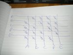
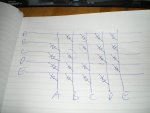
Just found an even easier way to draw the Charlieplex matrix.

The attached pic shows five pins, ABCDE, driving 20 LEDs.

There is a LED at each crossing, except for the lines with the same pin letter.

Adding an extra pin just means adding a new row and column, and putting in the next LEDs in the same way.


The two circled LEDs illustrate how Charliplexing works.

If B is Hi and C is Lo, then the lower left LED lights.

If B is Lo and C is Hi, then the upper right LED lights.

These two LEDs could be the inverse-parallel diodes in a Red/Green LED.
Treating all the others the same, you could have 10 R/G LEDs driven fron 5 pins.

Drawing the matrix like this shows that it's no more difficult to wire than a normal 5 x 5 multipelxer,


I'm going to try a 5 pin 20 LED setup tomorrow.

Cheers,

Buzby.
 

Attachments

Buzby

Senior Member
Hi Texasclodhopper,

Take one Charlieplexed or Multiplexed array of LEDS, say the 240 discussed earlier. Put them in a circle. 240 x 3mm LEDs should make a circle just under 300mm diameter.

Do the same for another array, on a slightly smaller circle. Repeat until you run out of LEDs.

Now you have 9 circles, one per planet. Lighting 1 of the LEDs in each circle shows the position of the relevant planet round the sun.

Drive each circle from it's own PICAXE. ( When I get more confident I'll probably not need one PICAXE per planet. )

The code in the PICAXE just 'moves' the lit LED round the circle.

The tricky part is calculating the relative speeds to 'move' each 'planet'.

( It's similar to the hundreds of circular LED clocks strewn across the Internet, but I want to make something different !. )

I hope this makes it clearer.

Cheers,

Buzby
 

hippy

Technical Support
Staff member
The two circled LEDs illustrate how Charliplexing works.

If B is Hi and C is Lo, then the lower left LED lights.

If B is Lo and C is Hi, then the upper right LED lights.
Good analysis, so no, two LED's per node don't work - Or do, but only if you have a triangular block of paired-up LED's - so it's the same total number of LED's no matter how you view it.
 

techElder

Well-known member
Buzby, now I understand that your program will be keeping some sort of sync from planet to planet.

Will you try to be really close to the real world timing?
 

Buzby

Senior Member
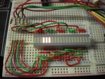
Here is my firsrt Charlieplex attempt, 20 LEDs from 5 IO lines.

The five lines come from a 20X2, via the five resistors at top left.
The lines are connected in groups of 4 to the anodes of the LEDs ( top side ).
The bottom side of the LEDs connect to the same five lines, but in a different order. ( If you compare the breadboard with the sketch, you can see the pattern. )

The code is based on hippy's idea, and it works fine.

I can see now that the PICAXE orrery is feasible, it just needs a lot of effort !.
 

Attachments

Last edited:

Buzby

Senior Member
A question for hippy, the font of all knowledge !

b0 = led number
Read b0, b1
anode = b1 / $10
cathode = b1 & $0F
High Anode
Low Cathode
Pause 1
Input anode
Input cathode

When this code runs, Anode and Cathode can get numbers in the range 0 to 15.

I know 0 to 7 then map to PortB.0 to .7, but where do 8 to 15 map to ?.

( I'm away from my hardware for the next week, so I'll have to try it in the simulator. )

Cheers,

Buzby.
 

hippy

Technical Support
Staff member
0-7 = B.0-B.7
8-15 = C.0-C.7

It's generally 'bad practice' to use pin numbers on X2 rather than port.pin but in this case it was more to show the principle as described.

If have LED 123 between B.7 and C.6 you could regain port.pin clarity with ...

Symbol B.7_ = B.7 * 16
Symbol B.7_C.6 = B.7_ | C.6

Table 123, ( B.7_C.6 )
 

Buzby

Senior Member
Hi hippy,

Thanks for that.

I might have to use the 'bad practice' method if I need to calculate the IO addresses 'on-the-fly', as opposed to looking them up in a table, it all depends on how well my software goes.

Cheers,

Buzby.
 

hippy

Technical Support
Staff member
A table will likely be quicker giving 'instant' access to what I/O pins control the LED's. You can have up to 512 LED's per PICAXE if using TABLE and EEPROM, more if external I2C Eeprom.

Generating the data shouldn't be too hard if you needed that, and using pin numbers rather than port.pin would be acceptabe in a case like this when it saves effort.

Added : However, if you number the LED's top left, down, then next colum, 0-N, it should be possible to calculate from something like ...

row = ( N % (rows-1) ) + ( N / (cols-1) )

Just a challenge of what the row/col equations would have to be.
 
Last edited:

Buzby

Senior Member
Yes, a TABLE will always be quicker than 'on-the-fly' calculation, but I'm keeping my options open !.

Either way, an algorithm to convert LEDnum into Anode and Cathode would be useful to quickly generate the data, either as Port.Pin or 0-15, for preloading the table.

Calculating one of these values is easy, just LEDnum / N-1.
The other is more tricky, especially if it needs to be done 'on-the-fly', as it is not a simple 'remainder'.

Time to put my maths hat on, if I can remember where I put it !.
 
Last edited:

hippy

Technical Support
Staff member
Brute-force determination isn't too bad and you can always rely on the power of a PICAXE ...

Code:
#Picaxe 20X2
#No_Table
#No_Data
#Terminal 9600

Symbol CONTROL_LINES = 3

Symbol MAX_ROW = CONTROL_LINES - 1
Symbol MAX_COL = CONTROL_LINES-1

Symbol btn = w0
Symbol row = b2
Symbol col = b3
Symbol n1  = b4
Symbol n2  = b5
Symbol n3  = b6
Symbol n4  = b7
Symbol n5  = b8

Pause 2000

btn = 0
For row = 0 To MAX_ROW
  BinToAscii row, n1,n2,n3
  If row < 10  Then : n2 = " " : End If
  SerTxd( "' ",n2,n3," " )
  For col = 0 To MAX_COL
    SerTxd( "------|-" )
  Next
  SerTxd( CR, LF, "'    " )
  For col = 0 To MAX_COL
    If row <> col Then
      BinToAscii btn, n1,n2,n3
      If btn < 100 Then : n1 = " " : End If
      If btn < 10  Then : n2 = " " : End If
      SerTxd( " ",n1,n2,n3," ",$5C,"| " )
      btn = btn + 1
    Else
      SerTxd( "      | " )
    End If
  Next
  SerTxd( CR, LF )
Next
SerTxd( "'    " )
For col = 0 To MAX_COL
  SerTxd( "      | " )
Next
SerTxd( CR, LF, "'    " )
For col = 0 To MAX_COL
  BinToAscii col, n1,n2,n3
  If col < 10  Then : n2 = " " : End If
  SerTxd( "     ",n2,n3," " )
Next
SerTxd( CR, LF, CR, LF )

btn = 0
For row = 0 To MAX_ROW
  For col = 0 To MAX_COL
    If row <> col Then
      BinToAscii btn, n1,n2,n3
      If btn < 100 Then : n1 = " " : End If
      If btn < 10  Then : n2 = " " : End If
      n4 = row + "0" : If n4 > "9" Then : n4 = n4+7 : End If
      n5 = col + "0" : If n5 > "9" Then : n5 = n5+7 : End If
      SerTxd( "Table ",n1,n2,n3,", ( $",n4,n5," )", CR, LF )
      btn = btn + 1
    End If
  Next
Next
Code:
'  0 ------|-------|-------|-
'          |    0 \|    1 \| 
'  1 ------|-------|-------|-
'       2 \|       |    3 \| 
'  2 ------|-------|-------|-
'       4 \|    5 \|       | 
'          |       |       | 
'          0       1       2 

Table   0, ( $01 )
Table   1, ( $02 )
Table   2, ( $10 )
Table   3, ( $12 )
Table   4, ( $20 )
Table   5, ( $21 )
 
Last edited:

Buzby

Senior Member
Very impressive !.

Getting the PICAXE to calculate the pins and draw the grid as well !.

But it's not what I need, sorry.

Your code does what my VBA did, except I didn't make it draw the grid as well.

Basically it's two for-next loops, skipping the times when they are both the same value. This is fine for pre-calculating the table, but no good for on-the-fly.

I would need some equations that could calculate the results just given the N.
Calculating ROW is easy, it's just INT(N / MAX_ROW-1).
But COL is, as you know, not straightforward because of the moving 'gap'.

However, the 'gap' relates to the invalid pin combination when COL = ROW.

Because of this pattern, I suspect there may be some kind of integer bit shifty xor solution, but I've not tried yet.

We'll master this Charlieplexing yet !.

Cheers,

Buzby
 

hippy

Technical Support
Staff member
Based on the following, MAX_SIGNAL = signal lines - 1 = 2 ...

Code:
'  0 ------|-------|-------|-
'          |    0 \|    1 \| 
'  1 ------|-------|-------|-
'       2 \|       |    3 \| 
'  2 ------|-------|-------|-
'       4 \|    5 \|       | 
'          |       |       | 
'          0       1       2
row = ledNumber / MAX_SIGNAL
col = ledNumber % MAX_SIGNAL
If col >= row Then
col = col + 1
End If
 
Top