433 MHz band monitoring receiver

manuka

Senior Member
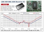
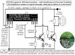
I've endlessly mentioned the benefits of being able to "listen in" on ones local 433.92MHz band, but yet again promote the likes of the simple Keymark/Spiriton receiver module for monitoring. With ever increasing band "noise" every 433 MHz user should have one in his toolbox- I've used mine endlessly for 433 MHz data monitoring & appliance activity- it's certainly a near indispensible "bang for buck" item.

Just today this again showed it's worth,this time with a no go neighbours 433.92Mhz wireless door chime (an Arlec DC149 ). These Arlecs use a super-regenerative receiver,which (being a superregen.) radiates a small RF signal even while receiving. It was the work of momments to bring the 433 monitor close to it & hear a suitable increase in background noise,ceasing when the Arlec batteries were removed. The fault turned out to be at the transmitter end...

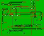
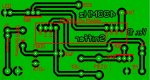
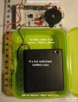
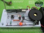
Mine is still breadboarded (as below) but it may be time to rustle up a PCB & assembly details- anyone interested? Stan.
 

Attachments

SAborn

Senior Member
Hi Stan,

The modules i have dont have the RSSI tap point, and i have not seen that on any i have looked at.
Otherwise they operate with all other 433mhz TR or TX modules.

So im not sure on a design that is not universal to all module versions.

When you ask ....Anyone interested.....are you asking about the idea or someone to design a PCB.

I use a 8 pin ic socket cut in half on my boards to plug the receiver module into so i can move it from board to board as needed.

Header sockets are to loose and cause problems.
 

manuka

Senior Member
Not tumable! It's broad band on 433 MHz so catches anything going. The red LED glows pretty faintly, & in fact I had to search for a high brightness one to even to see normal activity. A 100 LED Xmas tree cluster saved the day.

I've specifically based this around the Jaycar ZW3102 433 MHz ASK module to suit Aus/NZ users. These are ~Aust$10, & are reliable performers, although nothing special sensitivity wise. Their biggest weakness is a need for 5 ±½ V supply - readily handled by suitable AAs & perhaps dropping diodes. The module has an undocumented RSSI tap point that I was able to use, & the squelch feature gives it considerable class overall.

The need for a PCB may arise with an October 2010 JOTA Scout Jamboree scheduled near Sydney, as the organisers are pondering offering some hands on electronics project combined with hidden transmitter "fox hunting". I certainly would retain RX module plug in features, much in the DIP style you've mentioned, especially since scouts will be quite new to soldering etc so assembly will have to be pretty plug & play...
 
Last edited:

Dippy

Moderator
Nice idea Stan, I used to use something quite similar.

I'm surprised you aren't doing something a little smarter with the RSSI e.g. indicate an actual level.
 

chigley

Senior Member
"Several module pins are duplicated - avoid using however!"

Can I ask why, please?
Whenever I've breadboarded 433HMz RX modules I've always connected the two data pins together.
 

SAborn

Senior Member
Connecting the two data pins together is a bad idea in these modules as one is digital data and the other is linear data.

It was shown in several circuit magazines as done this way, but all include a errata on their sites stating not to do this and chop the linear pin off if using one of their kit boards.
 

manuka

Senior Member
Chigley: I strictly meant "avoid REusing for other functions"- it be tempting to run the RSSI to one of the spare (once isolated) pins, but soldering & track cutting etc was found too tricky for most folks-although I've near X-Ray closeup vision!

Dippy: The RSSI level could certainly be taken further, but the initial intention was just to provide a simple signal strength guide, which the present idiot light LED does nicely (especially in noisy conditions). The scouts have such a tight BOM budget (~UK £10 a head for everything),that using a PICAXE may blow it...

Extra: The 2 data pins on these KeyMark/SpiritOn ZW3102 come already joined together on the module.
 

Attachments

Last edited:

SAborn

Senior Member
So Stan, what do you want? someone to do the circuit artwork or someone to make the boards or both.

One would need to use some chunkie tracks and good size pads for the lesser skilled to construct, as it makes it easier to solder and less likely to lift the tracks off with heat and crap soldering irons.
 

chigley

Senior Member
Connecting the two data pins together is a bad idea in these modules as one is digital data and the other is linear data.

It was shown in several circuit magazines as done this way, but all include a errata on their sites stating not to do this and chop the linear pin off if using one of their kit boards.
Hmm, I just looked at the datasheet for the RX module I have (SparkFun) and the last page shows a diagram with the pins connected together.

Maybe my module is different to more complex ones?
 

manuka

Senior Member
SAborn: I'm really just tossing around ideas by mentioning PCBs- hence we'd (naturally) considered PEBBLE & Kiwi Board, but I'm indeed wary that fiddly scout level field soldering will be too demanding. Mini solderless protoboards may have some mileage in fact (if only due to their cool colours!). Stan
 

Attachments

Dippy

Moderator
Ah those borrasic scouts again... ;)

I take it these scouts will be running around in the undergrowth and chucking things around. How will solderless breadboard stand up to that?
Won't all your bits get squashed or fall out?
Won't a 30p PCB be cheaper?
Can't they solder it on their Mum's kitchen table before going into the field?
(Or a competent friend can solder it and make him/herself some cash).
 

SAborn

Senior Member
I think we under estimate what the youth of today can do, and think a project in soldering a simple circuit is worth its weight in gold for education reasons.

We all started somewhere too remember.

That is the whole objective.... the better your work, the better the circuit will work, and the better your chances on the fox hunt.

Kids are clever little buggers and just need to be shown how to do things.

How many boards are needed for the event.
 

manuka

Senior Member
SAborn: 100 up quantities could arise,& Jaycar may even run the whole thing as a kit. The point indeed is to solder together something electronic that's useful, particularly circuitry that's not available for peanuts elsewhere already. All too many beginners LED flashers/FM bugs etc are widely available in coin & toy shops,& image conscious kids often may disdain their own effort once the novelty wears off. I call it the "thank you card to granma phenomena"-most of us will recall as kids just wanting to buy a swish store card, yet our elders would insist we create a clunky home made thing " that granma will love"- & we'd hate.

Apparently adults (hams?) will be there to assist the scouts. "There" however may involve a trestle table set up in a tent under a windy tree, so soldering needs will have to be fairly simple,with large pads etc.
 

boriz

Senior Member
Minimalist broadband receiver: Antenna to MOSFET gate, Source to ground, Drain through 100K resistor to +12v. Drain to audio amp.

:)
 

SAborn

Senior Member
Stan,

Is it really required to use 433mhz TX&RX as it could easy be done with FM.
I have built bugs that transmit a 400 meters and this way the kids would just need to bring their own little pocket FM radio and ear phones.

Or is the exercise for them to actually build a electronic project.
 

manuka

Senior Member
Yes- they need to build a working project, & the utility of being able to also use the RX for later 433 MHz device fault finding etc is highly motivational as well. Furthermore, Yagi style "fox hunting" antenna at 433 MHz are pretty compact & directional, whereas 100 MHz versions are more akin to classic VHF TV antenna & would be a beggar to use in the bush.
 

SAborn

Senior Member
I dont know Stan, where you sense of adventure.

I think it would be fun sending a bunch of kids out into the bush armed with a tv antennas.

You could just imagin what they would come back like. Hmmm???

Be nothing more chalenging than crawling through the undergrowth hauling a tv antenna.

Just dont lend them the one off your house, unless you like watching snow storms.
 

Grogster

Senior Member
Pretty easy, as the circuit is very simple.
I could rustle up something in a day or two, provided you specifically want to use the Jaycar offerings - I design lots of PCB's. I would be happy to upload the file(s) here for the good of the forum. My main PCB program is Sprint Layout.
http://www.abacom-online.de/uk/html/sprint-layout.html

This can export Gerber files for manufacuring, or you can just produce them yourself - this is another great teaching tool - showing and having students produce the PCB themselves. Not hard at all, with the right bits and pieces...

@ STAN: How about using a darlington arragement for the LED driver - that should give you much more brightness in your LED, even with relitively weak signals. I've pretty much done the PCB already - will upload it here soon.
 
Last edited:

manuka

Senior Member
Grogster- very good of you to offer. The case is still being pondered, but it may be a simple translucent 200mL Sistema "Klipo" mini lunch box,available at our Kiwi red shed for <NZ$2. If this is used any PCB would have to be thumb sized at only ~25-30mm across,although it could be ~70mm wide. Stan
 

Taniwha

Senior Member
Yes- they need to build a working project, & the utility of being able to also use the RX for later 433 MHz device fault finding etc is highly motivational as well. Furthermore, Yagi style "fox hunting" antenna at 433 MHz are pretty compact & directional, whereas 100 MHz versions are more akin to classic VHF TV antenna & would be a beggar to use in the bush.
I hope they are using a different frequency to the DOC Kiwi setups, or they are going to find sowme unusal "foxes"

Kia Kaha
Stewart
 

Grogster

Senior Member
Oh well - done it anyway - perhaps it would be useful to someone...

This board is 80x65, but has the 9v battery and 5v regulator on-board.

See what you guys think. Uploaded plain JPG, but I can also upload the actual files, if anyone wants them, and with the free Sprint Layout Viewer, you can print your own films and make the PCB.
 

Attachments

SAborn

Senior Member
Hi Grogster

Is sprint layout freeware as i like the look of it.

I use PCBExpress as i like the simplicity of it and not being held to ridgid constraints within the software.
I can also generate the drill codes from it for my small cnc router, and see Sprint will allow me to do this to. (very important for the home user).

Im a cheap sod and like freeware.
 

Grogster

Senior Member
@ SAborn - No, it is not free - follow the link, it takes you right to the page about it. Although it is not free, it is very cheap for PCB CAD software compared to other MUCH more expensive PCB softwares. It is multi-layer, and I have the older version 4, which allows you to design double-sided boards each with it's own overlay if you want. The newer version 5 lets you design multi-layer boards!(not that I have ever needed to do that - yet!)

The viewer is free - you can download it from the same link, and this will let you see the .LAY files and print them to film if you want to make the board.

Not that I am trying to push this program, but I do all my PCB's on it, and it is simply fantastic.
Easy to learn and work with, will run on ancient old hardware if you need it to, and is WELL worth the dosh, IMHO.

EDIT: NZ$70 for Sprint Layout 5 - very cheap, really. That's AUS$57, or US$49.
Updates are free.
Extensive MACRO library available for version 5, but you can easily create your own components and add them to the library - I did that this morning for the 433MHz Rx module. All you need are dimensions and pin-spacings...
 
Last edited:

manuka

Senior Member
I'm impressed ! Fatter pads & wider "no man's land" insulation would be desirable to ease soldering woes of course. The SMA socket would probably blow the budget- just a simple RCA type may be enough for serving a 170mm whip or simple Yagi.

Sorry I'd not stressed the embargo on a 9V supply- these cussed 9V batteries have mediocre life & can run to NZ$5 each ( = both a serious BOM & ongoing cost issue). Worse still, folks tend to rob them from smoke alarms... AAs in contrast are dirt cheap & energetic. It transpires the Himark engine on the Jaycar module is also happy with as high as 7V, meaning even 4 x fresh alkaline AAs (which can be ~1.6 V each) will be quite OK, & no 7805 will be needed. Hence a 4 x AA switched battery pack looks to be the supply of choice. Ah-fancy a redesign ?! Stan.

Extra: As Dippy keenly observes, budgets are an issue -the BOM is Aust $20 ! (~£12-15)...
 

Attachments

Last edited:

Dippy

Moderator
Isn't an SMA socket going to break the banks of the scouts?

I get a little worried about those thin inter-track spaces, for the reasons Stan points out and certainly if it were a Tx it could impact.

And for battery apps do you really want to use that greedy old dinosaur of a regulator?

Nonetheless, very pretty.
 

Grogster

Senior Member
I will post an updated pattern tomorrow - just for the hell of it. :D

The "Standard" spacing between tracks and ground-plane is 0.4mm, and I have never had a problem of so much solder you bridge the gap - provided you are not using Dad's spouting soldering iron of several hundred watts! ;)

I can widen that to whatever - will make it about 1mm or so.

Cost was not really a consideration for me when I drew it - more of a "This is what we need" kind of drawing, and worry about cost later, as it was not going to be that costly. However, taking cost into account, I will see what else we can come up with. I will remove the battery holder and battery, and just have PCB pins for connection to a battery bank. The 7805 was chosen due to cheapness - about $2 each. I could put a SMD CMOS reg in there if you like - standby current 20 micro-amps. :p

I will plop another version up tomorrow as I say, without the battery, battery holder, regulator. That will also make things much smaller...

EDIT: New image with 1mm track-GP gap, no 9v battery holder, regulator or SMA socket. New PCB size is 75 x 40. I actually love designing PCB layouts - strange, I know! :D
 

Attachments

Last edited:

Grogster

Senior Member
I get a little worried about those thin inter-track spaces, for the reasons Stan points out and certainly if it were a Tx it could impact.
Never had any problems with range etc, with 25mW 433MHz Tx'ers.
Using RF track-width of 2.03mm @ 433MHz gives a pretty good match, and I have been able to get 750-1,000 meters easy on 25mW using the Radiometrix modules, assembled on PCB's with 0.4mm track-to-GP layouts. :)
.
(using 2.1dB 433MHz ground-independent aerial, mounted outside, approx 5-meters high.)
 

manuka

Senior Member
Grogster:We'll keep you on at this rate- I'm ex. Nelson & recognise the work style of a fellow mainlander! In fact if you can produce such PCB artwork darlings I may be able to direct your way similar level commisions (& probably folding stuff!). Best we PM to discuss this- I'm always too short of time to deisgn & rustle up PCBs for students, & often have to get them to do one offs commercially (or in China if in bulk) ...

Those wider track verges now are near ideal & even the most novice solderer should cope!
IF you are up to it (& after the All Whites goal us Kiwis increasingly are) can you maybe look at these extra points which will further inspire youthful confidence -

* Renaming those "548" as NPN1 & NPN2
* Labelling J2 also as squelch
* You can do away with J1 as the 4 xAA battery box comes c/w a switch!
* Saying RSSI Feed instead of just RSSI
* Call it "Sniffer" in quotes (I think this name is ideal & will take to using it!)
* Say 433 MHz with a space for clarity - perhaps move this & the "Sniffer" title ?
* Remove 7805, Shottky & 470n, 10 uF (& pad) silk screening info
* Add a + to the LED anode
* Add a bold + and GND near the supply points

Board size is still a bit of an issue, as ideally it should be no more that 30mm x70mm. If you bring the Piezo pads closer that'll save a few mm (the piezo will be flying lead connected anyway), & turning the antenna pad thru' 90° will also help. You can run the 10k near the piezo to the unused 10uF pad of course once this R is turned thru' 90°. The RSSI pad can be brought closer to the module after bending down 90° as well. Phew- you've erant your Speights! Stan.
 

Grogster

Senior Member
@ manuka - I am somewhat honored that you like what I have done. I recall that I might have "Annoyed" you in the past with posts on this forum, so this is nice. :)

Will PM you - best I think, given your comments.

Forums will still be kept up to date. :)

PCB size is not really that much of an issue. Based on what you want, I can compress/redesign to fit the dimensions you want PROVIDED you have an external 4.5v battery pack.
The Schokey diode was only there, as it has a 100mV drop across it's junction vs the more normal silicon diode voltage drop of 600mV - important for battery-based projects.

I am sticking to standard component sizes - if you want to go SMD, you can make things very small, but I don't think your students would appreciate that!!! :D
 

Grogster

Senior Member
For the forums information:

- Pads can be any size you like
- Hole-centers can be any size you like
- Track-GP spacing can be any size you like
- Overlay can contain any information, or no information - whatever.
- I produce PCB's.

I DON'T WANT THIS TO READ AS AN ADVERT FOR ME.
More an ad for Sprint Layout...
It's great software.
 

manuka

Senior Member
Grogster (Ah- Speightster?): What me annoyed- it must have been some Australasian namesake! OK on normal components- no SMD for this project. It's late - quick pix below FYI. Stan.
 

Attachments

Grogster

Senior Member
Assimilating...
(no, I am not Borg...)

EDIT: A very small lunch-box!!! :D
Will work on this.
Check your PM please.
 

Grogster

Senior Member
Grogster (Ah- Speightster?)
No.
Grogster is a name that was given to me when I was at high-school - something your students can relate to! :D

I was not a drunk or anything, my "Real" name is Graeme, so that was perverted into "Grogster" by by circle of friends, and then the rest of the school found out that I was drunk behind the sofa with a girl at a piss-up.

But it was not Speights, more Rum And CocaCola, as per the Andrews Sisters song.

I've said too much...
 
Last edited:

manuka

Senior Member
One assumes it's a North Island "Hard times/ too busy to stop" lunch box - only you Southern Men can eat like champions. Forum regulars - please excuse Kiwi jargon, & we'll continue via PM but update you. Stan.
 

Grogster

Senior Member
Here ya are. PCB size is 30mm x 70mm.
I'm quite enjoying this - always fun to design another board... :)
Battery-pack connections and Piezo connections are via 2-way PCB-mount terminal-blocks, but you could just as easily use PCB pins, which would be cheaper.

The thick red lines on the two transistors represent the face of the transistor - standard CBE arrangement, but people do put them in the wrong way sometimes. ;)

Let me know if you see anything wrong.
 

Attachments

Last edited:

SAborn

Senior Member
I see you have joined the data pins together and as far as i am aware with the use of these modules from jaycar this is a NO,NO.
If you check silicon chips circuits they also show this but if you look a little closer on the errators they say to chop off the analog pin as it was a design fault to join them together.

I know some one recently in the uk had this discussion with me and the modules he had a data sheet for said it was ok for a different type but the jaycar ones i have used must not be joined on the data pins.

You only use the digital data pin with a picaxe but not sure in this case.

I know looking at the waves on the cro they were different for each data pin.

I would also make the ant pad 5x bigger should it be needed to add a different ant later it will allow for this as in the case of a small whip they can bust a small pad off the board if knocked.
You have plenty of room there so why not use it.

Other wise nice work.
 
Last edited:
Top