PhilHornby
Senior Member
By counting the pulses from the meter (and knowing the starting reading), it is trivial to make the updated count available to a remote reader. My reason for starting this project was different though - I wanted to derive the instantaneous Power usage from the time between pulses. This
Assuming 1000 pulses = 1KWh (which seems common), then Power = 3600/Time. Unfortunately, this results in anything other than a simple straight-line graph (see: Multiplicative inverse - Wikipedia ), meaning that the time between pulses varies wildly! (At maximum power (24KW? in a UK domestic setting), the pulses are 150mS apart; at 1W, they are 1 hour apart!). I tackled this, by sending reports every 5 seconds from the 'idle' loop, thus filtering short-lived, high power bursts. As the power falls and the time lengthens, Power values are synthesised every 5 seconds and converge rapidly on the final result. (The first such synthesised value at 5 secs, equates to 720W - already a massive reduction from a potential previous reading of 24KW).
More details are given in the code and I can document the physical implementation, if anyone is interested.
Here is a 'block diagram' of the functionality required :-
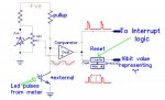
This is much simpler than it may at first appear (apart from the PhotoTransistor, everything is integral to the Picaxe 08M2)...
The Fixed Voltage Reference and DAC are combined to give a stable, but adjustable voltage which is higher than that available in ambient lighting, at the collector of a Phototransistor. The two voltages are compared using a Picaxe comparator and the output is brought out to a pin. Although not immediately obvious, this output signal can be used to trigger a software interrupt, whenever the phototransistor collector drops below the reference voltage, as a result of it 'seeing' a flash from the meter LED.
The Picaxe counter TIMER1 is used to count pulses from the Picaxe's PWM, which is running at 1KHz. This signal is 'gated' by the comparator, when its output is low. The result is that the time between LED flashes can be measured to 1mS resolution, up to a maximum of 65.535 seconds. Since this represents a Power of 3600/65.5 = 54W, an overflow counter is used to reset it every 60 seconds.
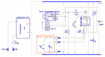
The practical implementation of the above block diagram, on a Picaxe 08M2 is shown below. (It also has a switch, which is used to 'nudge' the meter if required on initial setup and to assist with programming. An LED is provided as a replacement for that on the meter, which will be obscured by the phototransistor. Both are non-essential. Finally, a HC-12 sends the meter readings to a remote receiver).
Unfortunately, the Picaxe code cannot be posted 'inline' - due to 'Forum Limits', which seem to have been set some time in the 1980's
 , so you'll have to download the attachment if you're interested.
Attachments
-
28.1 KB Views: 16
Last edited: